


5-20
Section 5
Electrical Systems
Electrical Schematics & H arnesses
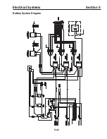
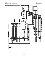
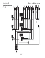
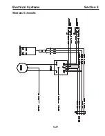
The following pages co ntain sch ematics pertaining to the elect rica l system in this boat. These
sch ematics were generated by elect rica l engineers and are for reference and to be used by
qualified electrical service technicians. Because of the custom nature of BCGP boats, these
diagrams may vary depending on the customer specific requirements. Any electrical work should
be co nduct ed by a trained marine elect rici an.
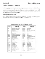
iring Identi cation Chart
BCGP adheres to electrical wiring requirements which meet all the ABYC E
standards. The
following ch art outlines the gauge, co lor and funct ion of the wiring used.
Summary of Contents for 37 Justice Series
Page 24: ...Section 1 Safety 1 12 O p erator s Notes...
Page 56: ...Section 2 Boat O p eration 2 32 O p erator s Notes...
Page 60: ...3 4 Section 3 F uel System Diesel F uel System Diagram F O RWARD...
Page 61: ...3 5 F uel System Section 3 Gasoline F uel System Diagram F O RWARD...
Page 74: ...4 2 Section 4 Boat Systems...
Page 75: ...4 3 Boat Systems Section 4...
Page 76: ...4 4 Section 4 Boat Systems...
Page 77: ...4 5 Boat Systems Section 4...
Page 78: ...4 6 Section 4 Boat Systems...
Page 107: ...4 35 Boat Systems Section 4 F O RWARD...
Page 134: ...4 62 Section 4 Boat Systems O p erator s Notes...
Page 145: ...5 11 Electrical Systems Section 5 Main DC Breaker Panel...
Page 146: ...5 12 Section 5 Electrical Systems Main AC Breaker Panel...
Page 148: ...5 14 Section 5 Electrical Systems H elm Breaker Panel...
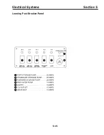
Page 149: ...5 15 Electrical Systems Section 5 L eaning Post Breaker Panel...
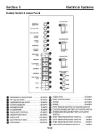
Page 150: ...5 16 Section 5 Electrical Systems Battery Switch Breaker Panel...
Page 155: ...5 21 Electrical Systems Section 5 Battery System Diagram...
Page 156: ...5 22 Section 5 Electrical Systems Battery Switch Panel Diagram...
Page 157: ...5 23 Electrical Systems Section 5 H elm Breaker Panel Diagram...
Page 158: ...5 24 Section 5 Electrical Systems H elm Switch Panel Diagram...
Page 159: ...5 25 Electrical Systems Section 5 L eaning Post Switch Panel Diagram...
Page 160: ...5 26 Section 5 Electrical Systems L ighting Schematic Deck...
Page 161: ...5 27 Electrical Systems Section 5 Windlass Schematic...
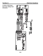
Page 162: ...5 28 Section 5 Electrical Systems O verb oard Discharge Panel and H olding T ank Schematic...
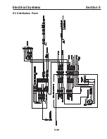
Page 163: ...5 29 Electrical Systems Section 5 DC Distrib ution Panel...
Page 164: ...5 30 Section 5 Electrical Systems DC Wiring Schematic Cab in...
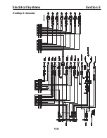
Page 165: ...5 31 Electrical Systems Section 5 H ardtop Schematic...
Page 166: ...5 32 Section 5 Electrical Systems 120 0 Shore ower Schematic...
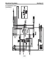
Page 167: ...5 33 Electrical Systems Section 5 AC Distrib ution Panel 120 0...
Page 168: ...5 34 Section 5 Electrical Systems 220 0 Shore ower Schematic...
Page 169: ...5 35 Electrical Systems Section 5 AC istribution anel 220 0...
Page 170: ...5 36 Section 5 Electrical Systems Bow T hruster Schematic...
Page 171: ...5 37 Electrical Systems Section 5 Bilge Wiring Schematic...
Page 172: ...5 38 Section 5 Electrical Systems Stereo Schematic...
Page 178: ...5 44 Section 5 Electrical Systems O p erator s Notes...
Page 212: ...6 34 Section 6 Maintenance Operator s Notes...
Page 214: ......