


5-5
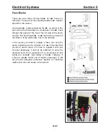
Electrical Systems
Section 5
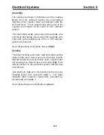
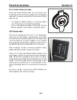
Automatic Charging Relays ( ACR)
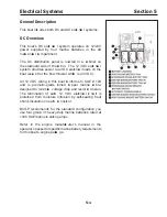
The three battery banks on this boat are automatica lly co nnect ed in parallel through the use
of ACRs (Automatic Charging Relay) when a sufficient charging source is present. The battery
banks are automatica lly separated when the ch arging source falls below a ce rtain voltage level
for a predetermined amount of time. The ACRs are mounted on the forward bulkh ead of the
mechanical equipment compartment.
The use of ACRs eliminates the need for the operator to monitor battery voltage and deci de
whether or not it is oka y to parallel the battery banks. It also eliminates the ch ance of a dead
battery bank if a paralleling switch were left in the Combined position without a sufficient
ch arging source present.
The operation of the ACRs ca n be manually overridden by use of the kn ob on the top of the ACR.
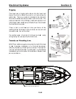
Manual Control O verride
E ach of the remote battery switch es and ACR units has a manual override kn ob on the top of the
unit as an added level of safety that allows manual ON-OF F co ntrol with or without power and
provides L OCK OF F for servici ng the elect rica l system. Refer to the manufact urer’ s manual in
the operator’ s pac ke t for co mplete instruct ions, safety co nsiderations and warranty information.
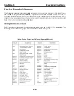
ACR
ACR
CENTER ENGINE
BATTERY #1
CENTER ENGINE
BATTERY #2
STBD ENGINE
BATTERY
PORT ENGINE
BATTERY
PORT REMOTE
BATTERY SWITCH
AUTOMATIC
CHARGING
RELAY
CENTER REMOTE
BATTERY SWITCH
AUTOMATIC
CHARGING
RELAY
STBD REMOTE
BATTERY SWITCH
TO PORT
ENGINE
TO CNTR
ENGINE
TO STBD
ENGINE
TO MAIN
GROUND
BUS
Summary of Contents for 37 Justice Series
Page 24: ...Section 1 Safety 1 12 O p erator s Notes...
Page 56: ...Section 2 Boat O p eration 2 32 O p erator s Notes...
Page 60: ...3 4 Section 3 F uel System Diesel F uel System Diagram F O RWARD...
Page 61: ...3 5 F uel System Section 3 Gasoline F uel System Diagram F O RWARD...
Page 74: ...4 2 Section 4 Boat Systems...
Page 75: ...4 3 Boat Systems Section 4...
Page 76: ...4 4 Section 4 Boat Systems...
Page 77: ...4 5 Boat Systems Section 4...
Page 78: ...4 6 Section 4 Boat Systems...
Page 107: ...4 35 Boat Systems Section 4 F O RWARD...
Page 134: ...4 62 Section 4 Boat Systems O p erator s Notes...
Page 145: ...5 11 Electrical Systems Section 5 Main DC Breaker Panel...
Page 146: ...5 12 Section 5 Electrical Systems Main AC Breaker Panel...
Page 148: ...5 14 Section 5 Electrical Systems H elm Breaker Panel...
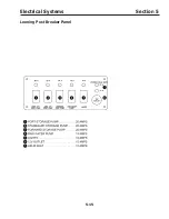
Page 149: ...5 15 Electrical Systems Section 5 L eaning Post Breaker Panel...
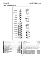
Page 150: ...5 16 Section 5 Electrical Systems Battery Switch Breaker Panel...
Page 155: ...5 21 Electrical Systems Section 5 Battery System Diagram...
Page 156: ...5 22 Section 5 Electrical Systems Battery Switch Panel Diagram...
Page 157: ...5 23 Electrical Systems Section 5 H elm Breaker Panel Diagram...
Page 158: ...5 24 Section 5 Electrical Systems H elm Switch Panel Diagram...
Page 159: ...5 25 Electrical Systems Section 5 L eaning Post Switch Panel Diagram...
Page 160: ...5 26 Section 5 Electrical Systems L ighting Schematic Deck...
Page 161: ...5 27 Electrical Systems Section 5 Windlass Schematic...
Page 162: ...5 28 Section 5 Electrical Systems O verb oard Discharge Panel and H olding T ank Schematic...
Page 163: ...5 29 Electrical Systems Section 5 DC Distrib ution Panel...
Page 164: ...5 30 Section 5 Electrical Systems DC Wiring Schematic Cab in...
Page 165: ...5 31 Electrical Systems Section 5 H ardtop Schematic...
Page 166: ...5 32 Section 5 Electrical Systems 120 0 Shore ower Schematic...
Page 167: ...5 33 Electrical Systems Section 5 AC Distrib ution Panel 120 0...
Page 168: ...5 34 Section 5 Electrical Systems 220 0 Shore ower Schematic...
Page 169: ...5 35 Electrical Systems Section 5 AC istribution anel 220 0...
Page 170: ...5 36 Section 5 Electrical Systems Bow T hruster Schematic...
Page 171: ...5 37 Electrical Systems Section 5 Bilge Wiring Schematic...
Page 172: ...5 38 Section 5 Electrical Systems Stereo Schematic...
Page 178: ...5 44 Section 5 Electrical Systems O p erator s Notes...
Page 212: ...6 34 Section 6 Maintenance Operator s Notes...
Page 214: ......