


Section 1
General Information
Programming & Operation 4-13
MN718
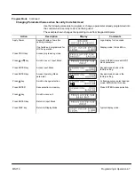
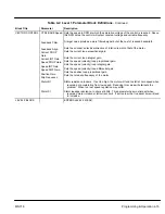
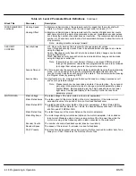
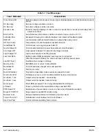
Table 4-2 Level 1 Parameter Block Definitions
- Continued
Block Title
Parameter
Description
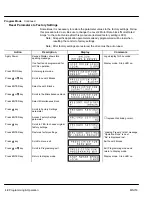
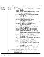
OUTPUT
OPTO OUTPUT
#1 – #4
Four optically isolated digital outputs that have two operating states, logical High or Low.
Each output may be configured to any of the following conditions:
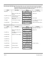
Condition
Description
Ready -
Active when power is applied and no faults are present.
Zero Speed -
Active when output frequency to motor is below the value of the
Level 1 Output “Zero SPD Set Pt” parameter.
At Speed -
Active when output speed is within the speed range defined by
the Level 1 Output “At Speed Band” parameter.
At Set Speed -
Active when output speed is at or above the Level 1 Output
“Set Speed” parameter.
Overload -
A normally closed contact that is active (opens) during an
Overload fault caused by a time out when output current is
greater than Rated Current.
Keypad Control -
Active when control is in Local keypad control.
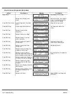
Fault -
Active when a fault condition is present.
Following ERR -
Active when the motor speed is outside the user specified
tolerance band defined by the At Speed Band parameter.
Motor Direction -
Active High when REV direction command received. Active Low
when FWD direction command received.
Drive On -
Active when control is “Ready” (has reached excitation level and
capable of producing torque).
CMD Direction -
Active at all times. Logical output state indicates Forward or
Reverse direction.
AT Position -
Active during a positioning command when control is within the
position band parameter tolerance.
Over Temp Warn - Active when control heat sink is within 3
°
C of Int Overtemp.
Process Error -
Active when process feedback signal is outside the range
specified by the Level 2 Process Control block, AT Setpoint
Band parameter. Turns off when process feedback error is
eliminated.
Drive Run -
Active when drive is Ready, Enabled, Speed or Torque command
received with FWD/REV direction issued.
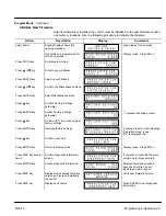
Zero SPD Set PT
Sets the speed at which the Zero Speed opto output becomes active (turns on). When the
speed is less than the ZERO SPD SET PT, the Opto Output becomes active. This is use-
ful when a motor brake is to interlock operation with a motor.
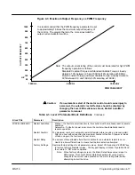
At Speed Band
The At Speed Band serves two Opto Output Conditions and the Level 2 Protection block
Following Error:
Sets the speed range in RPM at which the At Speed opto output turns on and remains
active within the range.
Sets the Following Error Tolerance Band for the Level 1 OUTPUT, Opto Output condition
Following ERR. The opto output is active if the motor speed is outside this band.
Sets the no fault operating speed range of the drive. This value is used by the Level 2
Protection block, Following Error parameter (if it is set to ON). If the drive speed falls
out of this band, the Level 2 Protection block, Following Error parameter will shut
down the drive (if it is set to ON).
Set Speed
Sets the speed that the AT Set Speed opto output becomes active (turns on). When the
speed is greater than the Level 1 Output SET SPEED parameter, the Opto Output
becomes active. This is useful when another machine must not start or stop until the
motor exceeds a predetermined speed.
Summary of Contents for 18H Series
Page 1: ...SERIES 18H AC Flux Vector Control Installation Operating Manual 9 97 MN718 VECTOR DRIVE ...
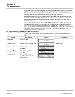
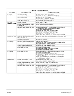
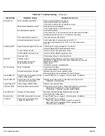
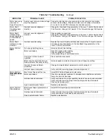
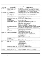
Page 105: ...Section 1 General Information 5 18 Troubleshooting MN718 ...
Page 109: ...Section 1 General Information 6 4 Manual Tuning the Series 18H Control MN718 ...
Page 144: ...Appendix C Appendix C 1 MN718 ...


