background image

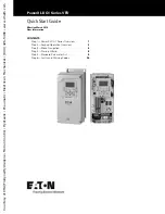
PowerXL DG1 Series VFD

Quick Start Guide

Effective March 2014
New Information

CONTENTS

Step 1—PowerXL DG1 Series Overview . . . . . . . 

1

Step 2—Keypad Operation Overview  . . . . . . . . . 

3

Step 3—Menu Navigation  . . . . . . . . . . . . . . . . . . 

6

Step 4—Startup Wizard  . . . . . . . . . . . . . . . . . . . . 

8

Step 5—Standard Parameter List   . . . . . . . . . . . . 

9

Step 6—Faults and Warning Codes . . . . . . . . . . . 

26

Courtesy 

of 

CMA/Flodyne/Hydradyne 

 Motion 

Control 

 Hydraulic 

 Pneumatic 

 Electrical 

 Mechanical 

 (800) 

426-5480 

 www.cmafh.com
Summary of Contents for PowerXL DG1-347D6FB-C21C

Page 1: ...erXL DG1 Series Overview 1 Step 2 Keypad Operation Overview 3 Step 3 Menu Navigation 6 Step 4 Startup Wizard 8 Step 5 Standard Parameter List 9 Step 6 Faults and Warning Codes 26 Courtesy of CMA Flody...

Page 2: ...Courtesy of CMA Flodyne Hydradyne Motion Control Hydraulic Pneumatic Electrical Mechanical 800 426 5480 www cmafh com...

Page 3: ...User Manual CD CD040002EN and accessory packet The accessory packet includes Rubber grommets Control cable grounding clamps Additional grounding screw Inspect the unit to ensure it was not damaged dur...

Page 4: ...Contains SN PN Type Date Contains EAN Code Date Code 20131118 Contains NAED Code Programmable Soft Key 2 Change Control Place Between Local and Remote Move Cursor Right Start Button Stop Button Back R...

Page 5: ...l delete this parameter from the Favorite menu Back Reset Back Reset This button has three integrated functions The button operates as backward button during normal mode In edit mode it is used as can...

Page 6: ...ter setting To confirm the start up list at the end of the Start Up Wizard To confirm the comparison item in parameters comparison mode The following is the same with Right key Enter parameter whole e...

Page 7: ...play PAR If monitor menu then display MON If fault menu then display FLT If operation menu then display OPE If quick start wizard then display QSW If optional card menu then display BOA If favorite me...

Page 8: ...D1 Error Value P9 Protections O4 Motor Current M10 Motor Temperature M33 PID1 Output P10 PID Controller1 05 Motor Torque M11 Torque Reference M34 PID1 Status P11 PID Controller2 O6 Motor Power M12 Ana...

Page 9: ...March 2014 www eaton com 7 Menu Navigation This section provides basic instruction on navigating each section in the menu structure Figure 5 Main Menu Navigation Courtesy of CMA Flodyne Hydradyne Mot...

Page 10: ...ctions Now the Startup Wizard is done It won t show again when next power up If you want to reset it please set the Startup Wizard P21 1 9 or select it from the main menu screen to enable and cycle th...

Page 11: ...quency 1 limit supervision Output frequency 2 limit supervision Torque limit supervision Reference frequency limit supervision Power limit supervision Analog input limit supervision Auto restart Power...

Page 12: ...ol voltage output 100 mA max 16 GND I O Signal Ground I O Ground for Reference and Control 17 AO1 Analog Output 1 Output Frequency Shows Output frequency to motor 0 60 Hz 4 mA to 20 mA 18 AO2 Analog O...

Page 13: ...um value of parameter Max Maximum value of parameter Unit Unit of parameter value given if available Default Value preset by factory ID ID number of the parameter Table 7 Monitor M Code Parameter Min...

Page 14: ...ing 25 Compatibility Fault 26 Device Change 27 Device Added 28 Device Removed 29 Device Unknown 30 IGBT Over Temp 31 Encoder Fault 32 AI 4 mA 4to20 mA 33 External Fault 34 Keypad Comm Fault 35 Fieldbu...

Page 15: ...Parameters P1 Code Parameter Min Max Unit Default ID Note P1 1 2 Min Frequency 0 00 Par P1 2 Hz 0 00 101 P1 2 2 Max Frequency Par P1 1 400 00 Hz Max Freq 102 P1 3 2 Accel Time 1 0 1 3000 0 s 3 0 103 P...

Page 16: ...Par P2 4 0 00 176 P2 4 2 AI1 Custom Max Par P2 3 100 00 100 00 177 P2 5 2 AI1 Filter Time 0 00 10 00 s 0 10 174 P2 6 2 AI1 Signal Invert 0 181 0 Not Inverted 1 Inverted P2 7 2 AI1 Joystick Hyst 0 00...

Page 17: ...N A IO1 1 11 DigIN A IO1 2 12 DigIN A IO1 3 13 DigIN A IO5 1 14 DigIN A IO5 2 15 DigIN A IO5 3 16 DigIN A IO5 4 17 DigIN A IO5 5 18 DigIN A IO5 6 19 DigIN B IO1 1 20 DigIN B IO1 2 21 DigIN B IO1 3 22...

Page 18: ...0 20 mA 1 0 10V P4 2 2 AO1 Function 1 146 0 Not Used 1 Output Frequency 2 Freq Reference 3 Motor Speed 4 Motor Current 5 Motor Torque 0 Nom 6 Motor Power 7 Motor Voltage 8 DC Bus Voltage 19 AI1 20 AI2...

Page 19: ...Motor Therm Protection 31 FB Digital Input 1 32 FB Digital Input 2 33 FB Digital Input 3 34 FB Digital Input 4 36 TC1 Status 37 TC2 Status 38 TC3 Status 39 In E Stop 40 Power Limit Superv 41 Temp Lim...

Page 20: ...ce 1 138 See P1 11 P7 2 12 Remote 2 Reference 7 139 See P1 12 P7 3 2 Keypad Reference Par P1 1 Par P1 2 Hz 0 00 141 P7 4 2 Keypad Direction 0 116 0 Forward 1 Reverse P7 5 2 Keypad Stop 1 114 0 Enabled...

Page 21: ...2 A Drive Nom VT 107 P8 3 12 V Hz Optimization 0 109 0 Disabled 1 Enabled P8 4 12 V Hz Ratio 0 108 0 Linear 1 Squared 2 Programmable 3 Linear Flux Optimization P8 5 12 Field Weakening Point 8 00 400 0...

Page 22: ...Current Limit 0 1 Active Motor Nom I 2 A Active Motor Nom I 13 10 314 P9 13 2 Stall Time Limit 1 0 120 0 s 15 0 315 P9 14 2 Stall Frequency Limit 1 00 Par P1 2 Hz 25 00 316 P9 15 12 Underload Protect...

Page 23: ...12 1 2 Preset Speed 1 0 00 Par P1 2 Hz 5 00 105 P12 2 2 Preset Speed 2 0 00 Par P1 2 Hz 10 00 106 P12 3 2 Preset Speed 3 0 00 Par P1 2 Hz 15 00 118 P12 4 2 Preset Speed 4 0 00 Par P1 2 Hz 20 00 119 P1...

Page 24: ...ID Note P20 2 1 RS485 Comm Set 0 586 0 Modbus RTU 1 BACnet MS TP P20 2 2 Slave Address 1 247 18 587 P20 2 3 Baud Rate 2 584 0 9600 1 19200 2 38400 3 76800 4 115200 P20 2 4 Parity Type 2 585 0 None 1 O...

Page 25: ...ped 1 Operational 2 Faulted P20 3 10 Connection Limit 0 2 2 609 P20 3 11 Modbus TCP Unit ID 1 610 P20 3 12 Comm Timeout Modbus TCP ms 2000 611 P20 3 13 Protocol Status 0 612 0 Stopped 1 Operational 2...

Page 26: ...Contrast Adjust 5 18 12 630 P21 1 13 Backlight Time 0 65535 min 10 631 P21 1 14 Fan Control 3 632 0 Continuous 1 Temperature 2 Run Follow 3 Calculate Temp P21 1 15 HMI ACK Timeout 200 5000 ms 200 633...

Page 27: ...ID Note P21 4 1 Real Time Clock 0 0 0 1 1 13 566 P21 4 2 Daylight Saving 0 582 0 Off 1 EU 2 US P21 4 3 Total MWh Count Mwh 601 P21 4 4 Total Power Day Count 603 P21 4 5 Total Power Hr Count 606 P21 4...

Page 28: ...e has detected too high a current 4 IH in the motor cable Sudden heavy load increase Short circuit in motor cables Unsuitable motor Check loading Check motor Check cables and connections Make identifi...

Page 29: ...mperature and motor load 14 Motor Stalled Configurable 1 No Action Motor is stalled Check motor and load 15 Motor OverTemp Configurable 1 No Action Motor is too hot based on either the drive s estimat...

Page 30: ...fault Configurable 1 Warning Communication between MCU and RTC chip isn t normal The power of RTC chip isn t normal The real time isn t normal Check the RTC chip 39 PT100 Fault Configurable 1 Fault Te...

Page 31: ...Courtesy of CMA Flodyne Hydradyne Motion Control Hydraulic Pneumatic Electrical Mechanical 800 426 5480 www cmafh com...

Page 32: ...enges Our focus is on delivering the right solution for the application But decision makers demand more than just innovative products They turn to Eaton for an unwavering commitment to personal suppor...

Reviews: