background image

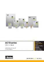
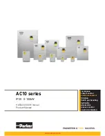
AC10 series

IP20   0-180kW

HA502320U001 Issue 6
Product Manual

aerospace

climate control

electromechanical

filtration
fluid & gas handling
hydraulics
pneumatics
process control
sealing & shielding

ENGINEERING 

YOUR 

SUCCESS.

Summary of Contents for 10G-46-0600-BF

Page 1: ...ies IP20 0 180kW HA502320U001 Issue 6 Product Manual aerospace climate control electromechanical filtration fluid gas handling hydraulics pneumatics process control sealing shielding ENGINEERING YOUR...

Page 2: ......

Page 3: ...ker Hannifin Ltd Although every effort has been taken to ensure the accuracy of this document it may be necessary without notice to make amendments or correct omissions Parker SSD Drives cannot accept...

Page 4: ...performance endurance maintenance safety and warning requirements of the application are met The user must analyze all aspects of the application follow applicable industry standards and follow the i...

Page 5: ...del Number see product label Where installed for your own information Unit used as a refer to Certification for the Inverter Component Relevant Apparatus Unit fitted Wall mounted Enclosure Application...

Page 6: ...pment SAFETY Where there is conflict between EMC and Safety requirements personnel safety shall always take precedence Never perform high voltage resistance checks on the wiring without first disconne...

Page 7: ...rating conditions the inverter may not operate as intended In particular Stored energy might not discharge to safe levels as quickly as suggested and can still be present even though the inverter appe...

Page 8: ...5 2 Chapter 6 The Menu Structure 6 1 6 1 Parameters Setting 6 1 6 1 1 Function Codes Switchover in between Code Groups 6 2 6 1 2 Panel Display 6 3 Chapter 7 Installation Connection 7 1 7 1 Installati...

Page 9: ...witching of the parameters displayed under running status 8 3 8 2 7 Operation process of measuring motor parameters 8 3 Operation process of simple running 8 4 8 3 Illustration of Basic Operation 8 5...

Page 10: ...12 6 1 Address and meaning 12 3 12 6 2 Running Status Parameters 12 4 12 6 3 Control commands 12 5 12 6 4 Illegal Response When Reading Parameters 12 6 12 7 Function Codes Related to Communication 12...

Page 11: ...ON OF CONFORMITY 14 10 Chapter 15 Parameter Reference 15 1 Basic parameters F100 F160 15 1 Running control mode F200 F230 15 4 Multifunctional Input and Output Terminals F300 F330 15 6 Analog Input an...

Page 12: ...o as the Product Code Input voltage 1 1 Phase 230V 240V 2 3 Phase 230V 240V 4 3 Phase 380V 480V Industry Rated current A XXXX OOO O Product model Frame Size mm 1 2 3 4 5 F Built in filter N without bu...

Page 13: ...5 0400 XX 11 41 40 62 10G 36 0550 XX 15 57 55 86 3Ph 400V 10G 41 0006 XX 0 2 1 1 0 8 0 6 2 5 10G 41 0010 XX 0 37 1 5 1 2 1 5 0 10G 41 0015 XX 0 55 2 1 1 8 1 5 5 5 10G 42 0020 XX 0 75 3 2 1 2 6 5 10G 4...

Page 14: ...ne side door hinge structure adopted for the front cover convenient for wiring and maintenance Taking 10G 46 0060 for instance its appearance and structure are shown below 2 1 Designed Standards for I...

Page 15: ...the modulation rate can be adjusted automatically so that the output voltage is unchanged Operation Function Frequency Setting Analog signal 0 5V 0 10V 0 20mA keypad terminal keys external control lo...

Page 16: ...Wait until it is completely discharged Use a meter capable of measuring up to 1500 VDC 600 VAC RMS to confirm that less than 50V is present on the DC BUS and between all power terminals and earth bef...

Page 17: ...50C 50C 50C 50C 50C 50C 1 1 30C 40C 45C 50C 50C 50C 50C 50C 50C 50C 50C 50C 50C 50C 50C 50C 50C 50C 50C 50C 50C 50C 1 5 30C 40C 50C 50C 50C 50C 50C 50C 50C 50C 50C 50C 50C 50C 50C 50C 50C 50C 50C 50C...

Page 18: ...Installation 3 3 AC10 Inverter 3 3 Inverters Installed in a Control Cabinet...

Page 19: ...rature humidity dust and vibration would decrease the life of inverter Daily maintenance is necessary to inverters Daily inspecting Inspect the motor for unusual noise when it is operating Inspect for...

Page 20: ...Opening size 1001 00 00 124 74 120 70 26 121 71 DIGIT DGT 4 LEDs indicate working status RUN while running FWD running forward DGT showing digit selection and FRQ when the MMI is showing frequency LED...

Page 21: ...170 110 22 102 142 5 2 1 Port of control panel Pins 1 2 3 4 5 6 7 8 8 core None 5V Grounding Grounding Signal 1 Signal 2 Signal 3 Signal 4 The default length of remote cable is 1m On the occasion of h...

Page 22: ...ace of function code keep pressing O key for 3s inverter will be stopped if stop command is controlled by keypad 6 1 Parameters Setting This inverter has numerous function parameters that the user can...

Page 23: ...roup or between Two Code Groups so that parameters setting becomes convenient and simple Press M key so that the keypad controller will display function code If user presses or key the function code w...

Page 24: ...rrent condition OC OC1 Indicates over current condition OC1 OE Indicates over voltage condition OH Indicates heatsink over heat condition OH1 Indicates external over heat condition OL1 Indicates inver...

Page 25: ...XXXX XX 106 150 180 195 1 76 94 170 M4 3 10G 43 XXXX XX 138 152 235 250 2 96 126 225 M5 4 10G 44 XXXX XX 156 170 265 280 4 9 146 255 M5 5 10G 45 XXXX XX 205 196 340 355 7 5 194 330 M5 6 10G 46 XXXX X...

Page 26: ...Installation Connection 7 2 AC10 Inverter Metal Cover Layout Frames 6 11...

Page 27: ...Frame 4 3 phase 400V 0 75kW 11kW 3 phase 230V 4kW 11kW Frame 5 3 phase 400V 15kW 22kW 3 phase 230V 7 5kW 11kW L1 R L2 S P B U V W 3 phase output Braking Resistor 1 phase input 220V 240V L3 T L1 R L2...

Page 28: ...Terminal P B External braking resistor Note no Terminals P or B for inverter without built in braking unit P DC bus line output External connections to optional braking unit P connected to input termi...

Page 29: ...rs Since the voltages and currents on the inverter power supply and output sides include harmonics measurement data depends on the instruments used and circuits measured When instruments for commercia...

Page 30: ...utput voltage Output side current I2 U V and W line currents Moving iron type AC Ammeter Current should be equal to or less than rated inverter current Difference between the phases is 10 or lower of...

Page 31: ...AI2 GND Self contained Power supply Ground Ground terminal of external control signal voltage control signal or current source control signal is also the ground of 10V power supply of this inverter 24...

Page 32: ...nals are only connected for NPN mode source or for PNP mode sink Select NPN or PNP mode by sliding the switch J7 to NPN or PNP Wiring for control terminals as follows 7 5 1 Wiring for positive source...

Page 33: ...ull up configurations are used and NPN mode is typically used The user should choose wiring mode according to the application requirement Instructions of choosing NPN mode or PNP mode 1 There is a tog...

Page 34: ...whereas not every terminal needs to be connected in each mode when applied Note 1 Only connect power terminals L1 R and L2 S to supply voltage for single phase inverters 2 The contact capacity for 22k...

Page 35: ...rame 3 1 8Nm 0 6Nm 0 6Nm 1 8Nm 1 3Nm 1 3Nm Frame 4 2 1Nm 0 6Nm 0 6Nm 2 1Nm 1 3Nm 1 3Nm Frame 5 3 4Nm 0 6Nm 0 6Nm 3 4Nm 1 3Nm 1 3Nm Frame 6 4 5Nm 0 6Nm 1 3Nm 4 5Nm 0 9Nm 0 9Nm Frame 7 10 Nm 0 6Nm 1 3Nm...

Page 36: ...oise generated by the drive may disturb the equipment nearby The degree of disturbance is dependent on the drive system immunity of the equipment wiring installation clearance and earthing methods 7 7...

Page 37: ...s should be shielded and the shielding layer should be grounded The signal cables should be placed inside a metal tube and should be located as far away as possible from the input output cables of the...

Page 38: ...es best Shared grounding pole good Shared earthing cable not good Note 1 In order to reduce the grounding resistance flat cable should be used because the high frequency impedance of flat cable is sma...

Page 39: ...esigned for protecting the product against high order harmonics surge leakage current Leakage Current Between Lines The line leakage current flowing through the distribution capacitors of the drive ou...

Page 40: ...ndard It can also suppress the radiation of the equipment Common mistakes in using power cable filter 1 Power cable too long The filter inside the cabinet should be located near to the input power sou...

Page 41: ...3 Modbus control 4 Keypad Terminal Modbus The modes of control command can be selected through the function codes F200 and F201 Operating status of inverter When the inverter is powered on it will ha...

Page 42: ...he Parameters Setting the parameters correctly is a precondition to give full inverter performance The following is the introduction on how to set the parameters using the keypad panel Operating proce...

Page 43: ...es of F801 to F805 correctly set the value of F801 7 5 F802 400 F803 15 4 F804 4 and F805 1440 respectively Note The motor nameplate may not indicate the number of poles The motor RPM listed on the na...

Page 44: ...carrying out tuning of the parameters make sure to disconnect the motor from mechanical load to make the motor under entirely no load status It is prohibited to measure the parameters when the motor i...

Page 45: ...the M key to enter the programming menu iii Enter the parameters of the motor Function code Parameter Values F800 Autotune type 1 2 F801 Rated motor power kW 7 5 F802 Rated motor voltage V 400 F803 R...

Page 46: ...for tuning of the motor iv Set functional parameters of the inverter Function code Parameter Values F111 Maximum frequency 50 00 F203 Main frequency source 0 F208 Terminal operational mode 1 v Close...

Page 47: ...jogging frequency and maintain the status of jogging operation vi Release the I key or until motor reaches 0 speed vii Switch off the main switch to power off the inverter 8 3 4 Setting the frequency...

Page 48: ...AI1 and AI2 In actual application select the analog input channel through F203 AI1 channel default value is 0 10V AI2 channel default value is 0 20mA Other states and modes of these switches are show...

Page 49: ...f Analog Speed Control Set F203 to 1 to select channel AI1 Set F203 to 2 to select channel AI2 Coding Switch SW1 Toggle switch S1 Analog signal range Coding Switch SW1 Switch 1 Switch 3 Switch 2 Switc...

Page 50: ...nction of F137 3 While studying motor parameters motor does not need to be disconnected with load One inverter can only drive one motor 6 PMSM sensorless vector control is suitable for the application...

Page 51: ...ncy is not limited by the Min frequency set by F112 If the starting frequency set by F109 is lower than Min frequency set by F112 inverter will start according to the setting parameters set by F109 an...

Page 52: ...ate base speed F805 Base frequency x 120 poles slip When running frequency is lower than this value inverter has constant torque output When running frequency exceeds this value inverter has constant...

Page 53: ...s and F123 0 inverter will run at 0Hz if F123 1 inverter will run reverse at this frequency This function is controlled by F122 F124 Jogging Frequency Hz Setting range F112 F111 Mfr s value 5 00Hz F12...

Page 54: ...131 Running Display Items 0 Current output frequency function code 1 Output rotary speed 2 Output current 4 Output voltage 8 DC Bus Voltage 16 PID feedback value 32 Temperature 64 Reserved 128 Linear...

Page 55: ...equency F111 50 00Hz numbers of motor poles F804 4 drive ratio F133 1 00 transmission shaft radius R 0 05m then Transmission shaft perimeter 2 R 2 3 14 0 05 0 314 meter Transmission shaft rotary speed...

Page 56: ...o restrain motor vibration Customers should correctly set motor power rotary speed numbers of motor poles motor rated current and stator resistance Please refer to the chapter Operation process of mea...

Page 57: ...or if the inverter output volts per hertz ratio is not the same as the motor specifications the motor will be damaged Carrier wave frequency of inverter is adjusted by setting this code function Adjus...

Page 58: ...irement user can push UP button to raise the frequency from 15Hz to 20Hz User can also set F155 5Hz and F156 0 0 means forward 1 means reverse In this way inverter can be run to 20Hz directly F159 Ran...

Page 59: ...direction setting Setting range 0 Forward running locking 1 Reverse running locking 2 Terminal setting 3 Keypad Mfr s value 0 The running direction is controlled by this function code together with ot...

Page 60: ...r down or through the up down terminals No memory of digital given means that the target frequency will restore to the value of F113 after stop no matter the state of F220 9 PID adjusting When PID adj...

Page 61: ...ing of secondary frequency source only suitable for F203 4 F204 1 When F207 5 X Y the frequency is set by subtracting secondary frequency source from main frequency source If the frequency is set by m...

Page 62: ...nd X are three terminals designated in programming DI1 DI5 1 Two line operation mode 1 this mode is the most popularly used two line mode The running direction of mode is controlled by FWD REV termina...

Page 63: ...ulse signal forward stop REV terminal impulse signal reverse stop CM terminal common port Note when pulse of SB1 triggers inverter will run forward When the pulse triggers again inverter will stop run...

Page 64: ...er or not to start automatically after repowered on is set by F213 F213 1 Auto starting after repowered on is valid When inverter is power off and then powered on again it will run automatically after...

Page 65: ...or malfunction is set by this function The function of frequency memory after power down is valid for main frequency and secondary frequency that is given by digital Because the digital given seconda...

Page 66: ...uctions from F307 to F309 4 Free stop Under free stop coast stop status after stop command is given the output is true until inverter completely stops 5 In running status 1 When the inverter is runnin...

Page 67: ...See F312 16 Overheat pre alarm Warning When temperature reaches 80 of setting value the output is true until overheat protection occurs or temperature is lower than 80 of setting value then the output...

Page 68: ...group function codes set characteristic frequency and its width For example F301 DO1 assignment 2 F307 Target Frequency 1 10 F309 Target frequency width 10 When frequency is higher than F307 DO1 becom...

Page 69: ...17 Three line type input X terminal 18 Acceleration deceleration 1 19 Reserved 20 Speed torque switchover 21 Frequency source switchover 32 Fire control switchover 33 Emergency fire control 34 Accel...

Page 70: ...malfunction signal is given to inverter the keypad will display ESP and the inverter will stop 10 Acceleration deceleration Hold When this input is true the Inverter will not be controlled by external...

Page 71: ...ing status the inverter will trip into OH1 48 High frequency switchover When this function is valid inverter will switch into high frequency optimizing mode 52 Jogging no direction In the application...

Page 72: ...d accel decel time F277 F278 1 1 The fourth accel decel time F279 F280 Table 9 5 Instructions for multistage speed K4 K3 K2 K1 Frequency setting Parameters 0 0 0 0 Multi stage speed 1 F504 F519 F534 F...

Page 73: ...9 terminal logic level is set by this group of function codes When F324 0 and F325 0 positive logic is selected and low level 0V is true when F324 1 and F325 1 negative logic is selected and high lev...

Page 74: ...ic 16 DI5 negative logic 32 DI6 negative logic 64 DI6 negative logic 128 DI8 negative logic Mfr s value 0 For example if user wants to set DI1 and DI4 to negative logic set F340 1 8 9 9 4 Analog Input...

Page 75: ...pper lower limit of input is in percentage If the value is greater than 1 00 it is positive if the value is less than 1 00 it is negative e g F401 0 5 represents 50 If the running direction is set to...

Page 76: ...s in the range of 2 to 3 volts the inverter will output 0Hz 0HZ voltage dead zone will be valid when corresponding setting for lower limit of input is less than 1 00 When F421 is set to 0 local keypad...

Page 77: ...n output current is selected analog output signal is from 0 to twice rated current When output voltage is selected analog output signal is from 0V to rated output voltage F433 Corresponding current fo...

Page 78: ...F412 Mfr s value 8 00 F473 AI2 insertion point B3 setting value Setting range F471 F413 Mfr s value 1 80 When analog channel input mode selects straight line please set it according to the parameters...

Page 79: ...s of Auto circulation Speed Control Setting range 0 9999 when the value is set to 0 the inverter will carry out infinite circulating Mfr s value 0 F503 Status After Auto circulation Running Finished S...

Page 80: ...0 F515 Frequency setting for stage 12 speed Hz Mfr s value 20 00 F516 Frequency setting for stage 13 speed Hz Mfr s value 25 00 F517 Frequency setting for stage 14 speed Hz Mfr s value 30 00 F518 Freq...

Page 81: ...given inverter will stop by deceleration time When F600 2 DC braking during stopping is selected After output frequency is lower than the initial frequency for DC braking F601 DC braking will stop th...

Page 82: ...value of stalling current adjusting and F607 1 then stalling adjusting function is valid Inverter will not accelerate until the output current is lower than initial value of stalling current adjustin...

Page 83: ...ctor control F106 0 Flycatching is disabled F614 Flycatching mode Setting range 0 Flycatching from frequency memory 1 Flycatching from max frequency 2 Flycatching from frequency memory and direction m...

Page 84: ...requency or reducing braking torque If the DC bus voltage is higher than the setting value of F632 VDC adjustor will automatically adjust the bus voltage same as the value of F632 VDC adjustment is di...

Page 85: ...Motor Overloading pre alarm setpoint Setting range 50 100 Mfr s value 80 F706 Inverter Overloading Coefficient Setting range 120 190 Mfr s value 150 F707 Motor Overloading Coefficient Setting range 20...

Page 86: ...t of common motor will be worse So when running frequency is lower than 10Hz the threshold of motor overload value will be reduced Please refer to Figure 9 13 F707 100 Figure 9 13 Motor overload prote...

Page 87: ...F711 Trip 1 Fault Frequency F712 Trip 1 Fault Current F713 Trip 1 Fault DC Bus Voltage F714 Trip 2 Fault Frequency F715 Trip 2 Fault Current F716 Trip 2 Fault DC Bus Voltage F717 Trip 3 Fault Frequenc...

Page 88: ...rter runs at the min frequency 4 Reserved Mfr s value 0 F742 Threshold of analog disconnected protection Setting range 1 100 Mfr s value 50 When the values of F400 and F406 are lower than 0 01V analog...

Page 89: ...ose indicated on the nameplate of the motor After being powered on it will use default parameters of the motor see the values of F806 F809 according to the motor power set in F801 This value is only a...

Page 90: ...hange to 1800 automatically When F104 3 and F810 50 00 F802 will change to 380V automatically F805 will change to 1460 automatically When F810 is set to the other values F802 and F805 will not change...

Page 91: ...rter model F817 PID switching frequency 1 Setting range 0 F111 5 00 F818 PID switching frequency 2 Setting range F817 F111 50 00 Figure 9 14 PID parameter Dynamic response of vector control speed can...

Page 92: ...mmunication Mode 1 ASCII 2 RTU 1 F902 Stop byte Setting range 1 2 2 F903 Parity Check 0 None 1 Odd 2 Even 0 F904 Baud Rate bps Setting range 0 1200 1 2400 2 4800 3 9600 4 19200 5 38400 6 57600 3 F904...

Page 93: ...restart if the feedback value drops below the value of FA05 PID minimum limit Therefore the value of FA05 should be increased from the default value of 0 0 when using the PID sleep function This is t...

Page 94: ...For example when FA29 2 0 and FA04 70 PID adjusting will not be valid during the feedback value from 68 to 72 You should try to achieve a critically damped response which allows the mechanics to trac...

Page 95: ...tart running Emergency fire mode 1 when the terminal is valid inverter will run at target frequency Emergency fire mode 2 when the terminal is valid inverter will run at the frequency of FA60 FA60 Run...

Page 96: ...reference source 0 Digital given FC09 adjust with keypad 1 Analog input AI1 2 Analog input AI2 0 FC07 Torque reference coefficient analogue input 0 3 000 3 000 FC09 Torque reference command value 0 3...

Page 97: ...y F111 FC28 Driving torque limit reference source 0 Digital given FC30 adjust with keypad 1 Analog input AI1 2 Analog input AI2 0 FC29 Driving torque limit coefficient 0 3 000 3 000 FC30 Driving torqu...

Page 98: ...set wrong Set the parameters correctly FL Flycatching Fault Flycatching failure Track again Contact manufacturer GP Ground fault Motor cable is broken and short circuit to earth The insulation of moto...

Page 99: ...ing Wiring correct Setting correct Too big with load Motor is damaged Malfunction protection occurs Get connected with power Check wiring Checking malfunction Reduce load Check against Table 10 1 Wron...

Page 100: ...0G 36 0550 XX 15 57 55 86 2 94 3Ph 400V 10G 41 0006 XX 0 2 1 1 0 8 0 6 2 5 120 10 5 0 1 145 94 10G 41 0010 XX 0 37 1 5 1 2 1 5 94 10G 41 0015 XX 0 55 2 1 1 8 1 5 5 5 94 10G 42 0020 XX 0 75 3 2 1 2 6 5...

Page 101: ...a LRC check End 0X3A Inverter Address Function Code Data Length Data 1 Data N High order byte of LRC Low order byte of LRC Return 0X0D Line Feed 0X0A RTU mode Start Address Function Data CRC check End...

Page 102: ...to produce the ones complement 3 Add 1 to produce the twos complement 12 5 2 RTU Mode Cyclical Redundancy Check CRC The CRC field is two bytes containing a 16 bit binary value The CRC is started by fi...

Page 103: ...d parameters setting Description of rules of function codes parameters address i Use the function code as parameter address General Series High order byte 01 0A hexadecimal Low order byte 00 50 max ra...

Page 104: ...0 Standby mode 0X01 Forward running 0X02 Reverse running 0X04 Over current OC 0X05 DC over current OE 0X06 Input Phase loss PF1 0X07 Frequency Over load OL1 0X08 Under voltage LU 0X09 Overheat OH 0X0A...

Page 105: ...d 7 1000 stage speed 8 1001 stage speed 9 1010 stage speed 10 1011 stage speed 11 1100 stage speed 12 1101 stage speed 13 1110 stage speed 14 1111 stage speed 15 Monitoring in which stage speed invert...

Page 106: ...byte changes into 1 Command meaning 0001 Illegal function code 0002 Illegal address 0003 Illegal data 0004 Slave fault note 2 Note 2 Illegal response 0004 appears below two cases Do not reset inverter...

Page 107: ...frequency source X 0 Digital setting memory 1 External analog AI1 2 External analog AI2 3 Reserved 4 Stage speed control 5 No memory by digital setting 6 Reserved 7 Reserved 8 Reserved 9 PID adjusting...

Page 108: ...her current to certain elements as well 12 9 Grounding and Terminal Terminal resistance of 120 will be adopted for terminal of RS485 network to diminish the reflection of signals Terminal resistance s...

Page 109: ...A3 The max value of function code is 1 Slave fault Example 2 Read output frequency output voltage output current and current rotate speed from N0 2 inverter Host Query Address Function First Register...

Page 110: ...ode is 1 Illegal function code assumption Example 4 Read the value of F113 F114 from NO 2 inverter Host Query Address Function Register Address Hi Register Address Lo Register Count Hi Register Count...

Page 111: ...ies speed control using a manual or auto set point Application 3 supplies speed control using preset speeds Application 4 supplies speed control using terminal Application 5 supplies speed control usi...

Page 112: ...The Default Applications 13 2 AC10 Inverter 13 1Application 1 Basic Speed Control F228 1...

Page 113: ...unction setting 58 Direction F318 DI3 terminal function setting 52 Jogging terminal no direction F319 DI4 terminal function setting 2 Stop terminal F320 DI5 terminal function setting 8 Free stop termi...

Page 114: ...The Default Applications 13 4 AC10 Inverter 13 2 Application 2 Auto Manual Control F228 2...

Page 115: ...3 terminal function setting 55 Auto manual switchover F319 DI4 terminal function setting 58 Direction F320 DI5 terminal function setting 8 Free stop F431 AO1 analog output signal selecting 0 Running f...

Page 116: ...The Default Applications 13 6 AC10 Inverter 13 3 Application 3 Preset Speeds F228 3...

Page 117: ...F207 Frequency source selecting 1 X Y F316 DI1 terminal function setting 56 Manual running F317 DI2 terminal function setting 3 Mutiple stage speed 1 F318 DI3 terminal function setting 4 Mutiple stage...

Page 118: ...The Default Applications 13 8 AC10 Inverter 13 4 Application 4 Raise Lower Secondary F228 4...

Page 119: ...Digital setting memory F208 Terminal two line three line operation selecting 1 Two line operation mode 1 F316 DI1 terminal function setting 15 FWD terminal F317 DI2 terminal function setting 13 UP fre...

Page 120: ...The Default Applications 13 10 AC10 Inverter 13 5Application 5 PID F228 5...

Page 121: ...n setting 58 Forward running F318 DI3 terminal function setting 52 Direction F319 DI4 terminal function setting 2 Stop F320 DI5 terminal function setting 8 Free stop F431 AO1 analog output signal sele...

Page 122: ...industrial environments EN 61000 6 4 2007 Electromagnetic compatibility EMC Part 6 4 General standards Emission standard for residential commercial and light industrial environments UL508C Standard f...

Page 123: ...trically in parallel 14 2 2 EMC Directive When installed in accordance with this manual the product will comply with the electromagnet compatibility directive 2004 108 EC The following information is...

Page 124: ...es buildings used for domestic purposes Note Houses apartments commercial premises or offices in a residential building are examples of first environment locations Second Environment Environment that...

Page 125: ...duct supplied as a component a suitable external filter is required Product supplied as a component a suitable external filter is required Product supplied as a component a suitable external filter is...

Page 126: ...ice The following markings shall appear in one of the following locations shipped separately with the device on a separable self adhesive permanent label that is shipped with the device or anywhere on...

Page 127: ...it protection must be provided in accordance with the National Electrical Code and any additional local codes or equivalent h CAUTION Risk of Electric Shock should be provided followed by instructions...

Page 128: ...15 XX Input and Output Terminal Block 6 14 STR SOL 10G 42 0020 XX 10G 42 0030 XX 10G 42 0040 XX 10G 42 0065 XX Input and Output Terminal Block 10 14 STR SOL 10G 43 0080 XX 10G 43 0090 XX Input and Out...

Page 129: ...10G 49 1800 XX Input and Output Terminal Block 189 0 250kcmil STR SOL 10G 49 2200 XX Input and Output Terminal Block 189 0 300kcmil or 2x1 0 10G 410 2650 XX Input and Output Terminal Block 189 0 500kc...

Page 130: ...5 XX 10G 31 0025 XX 10G 31 0035 XX 10G 31 0045 XX 10G 32 0050 XX 10G 32 0070 XX 10G 32 0100 XX 10G 11 0015 XX 10G 11 0025 XX 10G 11 0035 XX 10G 11 0045 XX 10G 12 0050 XX 10G 12 0070 XX 10G 12 0010 XX...

Page 131: ...annifin Manufacturing Limited address as below declare under our sole responsibility that the above Electronic Products when installed and operated with reference to the instructions in the Product Ma...

Page 132: ...assword 0 9999 8 F109 Starting Frequency Hz 0 0 10 00Hz 0 0 F110 Holding Time of Starting Frequency s 0 0 999 9 0 0 F111 Max Frequency Hz F113 590 0Hz 50 00 F112 Min Frequency Hz 0 00Hz F113 0 50 F113...

Page 133: ...e 16 PID feedback value 32 Temperature 64 Reserved 128 Linear speed 256 PID given value 512 Reserved 1024 Reserved 2048 Output power 4096 Output torque 0 1 2 4 8 15 F132 Display Items for Stop Mode 0...

Page 134: ...146 F150 30 00 F149 User defined voltage point V5 0 100 63 F150 User defined frequency point F6 F148 F118 40 00 F151 User defined voltage point V6 0 100 81 F152 Output voltage corresponding to turnove...

Page 135: ...ency source X 0 Digital setting memory 1 External analog AI1 2 External analog AI2 3 Reserved 4 Stage speed control 5 No memory by digital setting 6 Reserved 7 Reserved 8 Reserved 9 PID adjusting 10 M...

Page 136: ...ction memory 0 Disabled 1 Enabled 0 F213 Auto starting after repowered on 0 Disabled 1 Enabled 0 F214 Auto starting after reset 0 Disabled 1 Enabled 0 F215 Auto starting delay time 0 1 3000 0 60 0 F21...

Page 137: ...eady to run 14 In running status 2 15 At speed 16 Overheat pre alarm 17 Over target output current 18 Analog input disconnection 19 Reserved 20 At Zero output current 21 DO1 controlled by PC PLC 22 Re...

Page 138: ...temperature protection 48 High frequency switchover 52 Jogging no direction 53 Watchdog 54 Frequency reset 55 Manual auto switchover 56 Manual running 57 Auto running 58 Direction 11 F317 DI2 termina...

Page 139: ...inition Setting Range Mfr s Value Change F340 Selection of terminal negative logic 0 None 1 DI1 negative logic 2 DI2 negative logic 4 DI3 negative logic 8 DI4 negative logic 16 DI5 negative logic 32 D...

Page 140: ...0 00V F409 Corresponding setting for upper limit of AI2 input Max 1 00 F407 2 00 2 00 F410 AI2 channel proportional gain K2 0 0 10 0 1 0 F411 AI2 filtering time constant 0 01 10 0 0 10 F418 AI1 channe...

Page 141: ...t line mode 1 Folding line mode 0 F461 AI2 channel input mode 0 Straight line mode 1 Folding line mode 0 F462 AI1 insertion point A1 voltage value F400 F464 2 00V F463 AI1 insertion point A1 setting v...

Page 142: ...ency setting for stage 7 speed F112 F111 35 00Hz F511 Frequency setting for stage 8 speed F112 F111 40 00Hz F512 Frequency setting for stage 9 speed F112 F111 5 00Hz F513 Frequency setting for stage 1...

Page 143: ...0 Disabled 1 Enabled 2 Reserved 3 Voltage current control 4 Voltage control 5 Current control 0 F608 Stall Current Level 60 200 160 F609 Stall Voltage Level 110 200 1 phase 130 3 phase 140 F610 Stall...

Page 144: ...from F801 to F810 F844 1 F641 F649 Reserved F650 High frequency performance Setting range 0 Invalid 1 Terminal enabled 2 Enabled mode 1 3 Enabled mode 2 2 F651 Switchover frequency 1 F652 150 00 100...

Page 145: ...re set wrong 45 Communication Timeout CE 46 Flycatching fault FL 49 Watchdog fault Err6 67 Overcurrent OC2 F709 Trip 2 Type F710 Trip 3 Type F711 Trip 1 Fault Frequency F712 Trip 1 Fault Current F713...

Page 146: ...rheat 0 100 80 F747 Carrier Frequency Auto adjusting 0 Disabled 1 Enabled 1 F754 Zero current Threshold 0 200 5 F755 Duration time of zero current 0 60 0 5 Motor parameters F800 F830 Function Code Fun...

Page 147: ...rter model F817 PID Switching Frequency 1 0 F111 5 00 F818 PID Switching Frequency 2 F817 F111 50 00 F819 F860 Reserved Subject to inverter model F870 PMSM back electromotive force mV rpm 0 1 999 9 Su...

Page 148: ...10 0 FA04 Digital setting value of PID adjusting FA05 FA03 50 0 FA05 Min limit of PID adjusting 0 0 FA04 0 0 FA06 PID polarity 0 Positive feedback 1 Negative feedback 1 FA07 Sleep function selection...

Page 149: ...1 Delay time of torque speed control switchover S 0 0 1 0 0 1 FC02 Torque accel decel time s 0 1 100 0 1 0 FC03 FC05 Reserved FC06 Torque reference source 0 Digital given FC09 1 Analog input AI1 2 Ana...

Page 150: ...ved FC33 Re generating torque limit source 0 Digital given FC35 1 Analog input AI1 2 Analog input AI2 0 FC34 Re generating torque limit coefficient 0 3 000 3 000 FC35 Re generating torque limit 0 300...

Page 151: ...y parker com IE Ireland Dublin Tel 353 0 1 466 6370 parker ireland parker com IN India Mumbai Tel 91 22 6513 7081 85 IT Italy Corsico MI Tel 39 02 45 19 21 parker italy parker com JP Japan Tokyo Tel 8...

Reviews: