


Section 1
General Information
3-42 Receiving & Installation
MN718
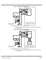
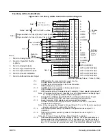
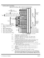
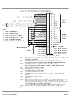
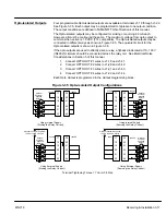
Figure 3-25 Bipolar Speed or Torque Connection Diagram
8
9
10
11
12
13
14
15
16
17
18
19
20
21
22
ENABLE
FORWARD ENABLE
REVERSE ENABLE
CLOSED=ORIENT
SPEED/TORQUE
*
TABLE SELECT
EXTERNAL TRIP
OPTO INPUT COMMON
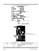
Programmable 0–5V Output (Factory Preset: Speed)
J1
ANALOG GND
ANALOG INPUT 1
POT REFERENCE
ANALOG INPUT +2
ANALOG INPUT –2
ANALOG OUT 1
ANALOG OUT 2
OPTO OUT COMMON
OPTO OUT #1
OPTO OUT #2
OPTO OUT #3
OPTO OUT #4
1
2
3
4
5
6
7
Programmable 0–5V Output (Factory Preset: Current)
Terminal Tightening Torque = 7 Lb-in (0.8 Nm).
30
31
32
33
34
35
36
37
38
39
40
41
42
43
44
23
24
25
26
27
28
29
COMMON
+24VDC
A
A
B
B
INDEX
INDEX
+5VDC
OPTO IN POWER
OPTO OUT #1 RETURN
OPTO OUT #2 RETURN
OPTO OUT #3 RETURN
OPTO OUT #4 RETURN
COMMON
A
A
B
B
INDEX
INDEX
Not Used
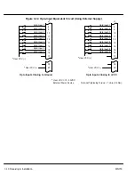
Encoder
Input
Note 5
Buffered
Encoder
Output
Note 6
*
TABLE SELECT
FAULT RESET
5k
W
Command Pot
Note 2
Note 1
±
5VDC,
±
10VDC or 4-20mA
Note 3
Note 4
*
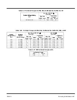
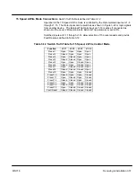
See Table 3-13.
Notes (for Figure 3-25):
1.
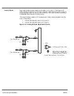
Refer to Analog Inputs.
2.
Refer to Analog Outputs.
3.
Refer to Opto Isolated Outputs.
4.
Refer to Figure NO TAG for 4-20mA.
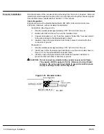
5.
Refer to Encoder installation.
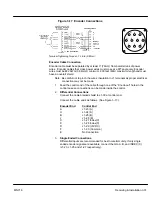
6.
Refer to Buffered Encoder Output.
Refer to Figure NO TAG.
J1-8
OPEN disables the control & motor coasts to a stop.
CLOSED allows current to flow in the motor and produce torque.
J1-9
CLOSED to enable operation in the Forward direction.
OPEN TO DISABLE Forward operation (drive will brake to a stop if a Forward command
is still present).
J1-10
CLOSED to enable operation in the Reverse direction.
OPEN to disable Reverse operation (drive will brake to a stop if a Reverse command is
still present).
J1-11
Causes the motor shaft to orient to a marker or external switch.
J1-12
CLOSED puts the control in torque mode.
OPEN puts the control in velocity mode.
J1-13 &
Select from four parameter tables as defined
J1-14
in Table 3-13.
J1-15
Momentary CLOSED to reset fault condition.
OPEN to run,
J1-16
OPEN causes an external trip to be received by control. The control will disable and
display external trip when programmed “ON”. When this occurs, the motor stop
command is issued, drive operation is terminated and an external trip fault is displayed
on the keypad display (also logged into the fault log).
If J1-16 is connected, you must set Level 2 Protection block, External Trip to “ON”.
J1-39 &
Jumper as shown to power the Opto Inputs from the in24VDC supply.
40
Summary of Contents for 18H Series
Page 1: ...SERIES 18H AC Flux Vector Control Installation Operating Manual 9 97 MN718 VECTOR DRIVE ...
Page 105: ...Section 1 General Information 5 18 Troubleshooting MN718 ...
Page 109: ...Section 1 General Information 6 4 Manual Tuning the Series 18H Control MN718 ...
Page 144: ...Appendix C Appendix C 1 MN718 ...


