


Section 1
General Information
Receiving & Installation 3-7
MN718
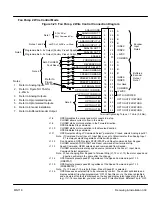
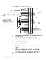
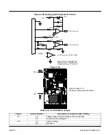
Figure 3-29 Analog Inputs Equivalent Circuits
500W
–
+
5.1V Zener
.033
m
F
5K
W
1.96K
W
+15VDC
20K
W
10K
W
10K
W
JP1
4-20mA
+
–
X N/C
To Microprocessor
10K
W
10K
W
To Microprocessor
Notes:
+
–
All OP Amps are TL082 or TL084
Analog Ground is separated from
Chassis Ground. Electrically they
are separated by an RC network.
30K
W
-15VDC
J1
2
3
4
5
1
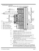
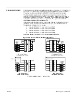
Figure 3-30
JP2
JP1
Refer to Table 3-15
for jumper placement information.
1 2 3
123
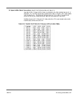
Table 3-15 Control Board Jumper
Jumper
Jumper Position
Description of Jumper Position Setting
JP1
1–2
Voltage Speed Command Signal. (Factory Setting)
2–3
4-20mA input at Analog #2
JP2
1–2
Factory Setting
2–3
Not used.
Summary of Contents for 18H Series
Page 1: ...SERIES 18H AC Flux Vector Control Installation Operating Manual 9 97 MN718 VECTOR DRIVE ...
Page 105: ...Section 1 General Information 5 18 Troubleshooting MN718 ...
Page 109: ...Section 1 General Information 6 4 Manual Tuning the Series 18H Control MN718 ...
Page 144: ...Appendix C Appendix C 1 MN718 ...


