


Section 1
General Information
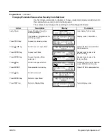
3-6 Receiving & Installation
MN718
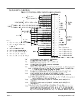
Analog Input #2
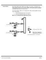
Analog input #2 accepts a differential command
±
5VDC,
±
10VDC or 4-20 mA. The
operating mode is defined in the of the Level 1 Input block OPERATING MODE
parameter.
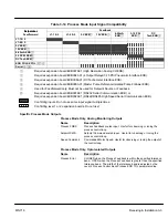
Note: Analog Input #2 is used with Standard Run 3-Wire, Fan Pump 2 or 3 Wire or
Bipolar Control modes and not used for the Keypad or 15 Speed 2 Wire or the
Serial operating modes.
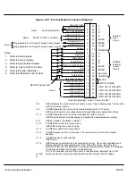
1.
Connect the Analog Input +2 wire to J1-4 and the –2 wire to J1-5.
2.
If using a 4-20 mA command signal, jumper JP1 located on the main control
board must be on pins 2 & 3. For all other modes, JP1 must be on pins 1 & 2.
Refer to Figure NO TAG for jumper position information.
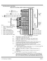
Note: Analog Input #2 can be connected for single ended operation by grounding
either of the inputs, provided the common mode voltage range is not
exceeded. The common mode voltage can be measured with a voltmeter.
Apply the maximum command voltage to analog input 2 (J1A-4, 5). Measure
the AC and DC voltage across J1A-1 to J1A-4. Add the AC and DC readings
together. Measure the AC and DC voltage from J1A-1 to J1A-5. Add the AC
and DC readings together.
If either of these measurement totals exceeds a total of
±
15 volts, then the
common mode voltage range has been exceeded. If the common mode
voltage range has been exceeded, the solution is either to change the
command voltage source or isolate the command voltage with a commercially
available signal isolator.
Summary of Contents for 18H Series
Page 1: ...SERIES 18H AC Flux Vector Control Installation Operating Manual 9 97 MN718 VECTOR DRIVE ...
Page 105: ...Section 1 General Information 5 18 Troubleshooting MN718 ...
Page 109: ...Section 1 General Information 6 4 Manual Tuning the Series 18H Control MN718 ...
Page 144: ...Appendix C Appendix C 1 MN718 ...


