


Section 1
General Information
Appendix A-5
MN718
Dynamic Braking (DB) Hardware Continued
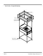
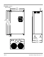
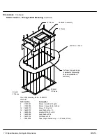
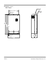
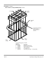
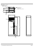
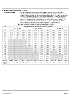
RBA Assemblies
An RBA Assembly includes a dynamic brake transistor and resistors completely
assembled and mounted in a NEMA 1 enclosure. The are designed for EO and MO
controls. Select the RBA based on the voltage rating of the control and the dynamic
brake watt capacity required. Use Table A-3 to select the RBA assembly. If more than
4,000 Watts of brake capacity is required, use a combination of RTA (DB transistor) and
RGA (DB resistor) assemblies. Refer to Section 3 “Optional Dynamic Brake Hardware”
for wiring diagram.
Table A-3 Dynamic Braking Assemblies (RBA)
MAXIMUM BRAKING TORQUE IN % OF MOTOR RATING
Cont.
Watts
Catalog
No
HP
20
25
30
40
50
60
75
100
150V
150
200
250
Watts
No.
200
90%
75%
60%
45%
36%
600
RBA2-610
G
E
to
240
150%
125
%
100%
75%
62%
1800
RBA2-1806
O
LTA
G
150%
150
%
150%
115
%
92%
4000
RBA2-4004
P
UT V
O
380
to
150%
150
%
120%
90%
72%
60%
48%
36%
28%
600
RBA4-620
INP
U
to
480
150%
150
%
120%
90%
72%
60%
48%
36%
28%
1800
RBA4-1820
150%
150
%
150%
150
%
150
%
120
%
96%
72%
56%
48%
36%
29%
4000
RBA4-4010
550
to
150%
150
%
120%
90%
72%
60%
48%
36%
28%
600
RBA5-624
to
600
150%
150
%
120%
90%
72%
60%
48%
36%
28%
1800
RBA5-1824
150%
150
%
150%
150
%
150
%
120
%
96%
72%
56%
4000
RBA5-4014
Summary of Contents for 18H Series
Page 1: ...SERIES 18H AC Flux Vector Control Installation Operating Manual 9 97 MN718 VECTOR DRIVE ...
Page 105: ...Section 1 General Information 5 18 Troubleshooting MN718 ...
Page 109: ...Section 1 General Information 6 4 Manual Tuning the Series 18H Control MN718 ...
Page 144: ...Appendix C Appendix C 1 MN718 ...


