


Section 1
General Information
3-10 Receiving & Installation
MN718
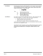
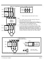
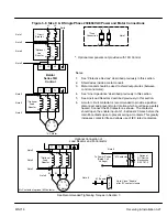
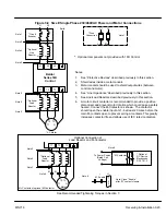
AC Main Circuit
Protection Devices
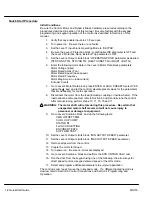
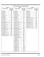
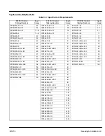
Be sure a suitable input power protection device is installed. Use the recommended circuit
breaker or fuses listed in Tables 3-4 through 3-6 (Wire Size and Protection Devices). Wire
sizes and protective device specifications are based on the controls’ maximum output power
rating for the operating zone. Refer to Quad ratings in Section 7 of this manual. If the output
power from the control will be less than the maximum, the sizes of the wire and protective
devices may be adjusted accordingly. Be sure to follow NEC, UL and other applicable codes.
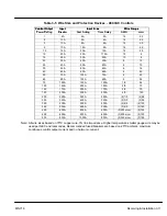
Input and output wire size is based on the use of copper conductor wire rated at 75
°
C. The
table is specified for NEMA B motors.
Circuit Breaker:
1 phase, thermal magnetic.
Equal to GE type THQ or TEB for 230 VAC
3 phase, thermal magnetic.
Equal to GE type THQ or TEB for 230 VAC or
GE type TED for 460 VAC and 575 VAC.
Fast Action Fuses:
230 VAC, Buss KTN
460 VAC, Buss KTS to 600A (KTU 601 - 1200A)
575VAC, Buss FRS
Very Fast Action:
230 VAC, Buss JJN
460 VAC, Buss JJS
575 VAC, , Buss JJS
Time Delay Fuses:
230 VAC, Buss FRN
460 VAC, Buss FRS to 600A (KTU 601 - 1200A)
575 VAC, Buss FRS to 600A (KTU 601 - 1200A)
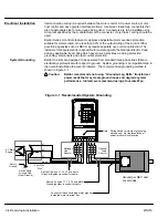
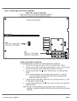
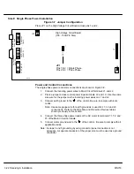
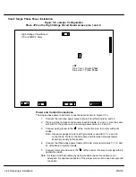
Power Disconnect
A power disconnect should be installed between the input power service and the control for
a fail safe method to disconnect power. The control will remain in a powered-up condition until
all input power is removed from the control and the internal bus voltage is depleted.
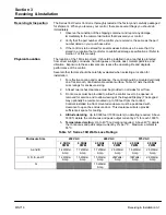
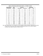
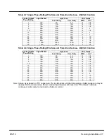
Wire Size and Protection Devices
Table 3-4 Wire Size and Protection Devices - 230 VAC Controls
Control O tp t
Inp t Breaker
Inp t F se
Wire Ga ge
Control Output
P
R ti
Input Breaker
Input Fuse
Wire Gauge
p
Power Rating
p
Fast Acting
Time Delay
AWG
mm
2
1
5A
5A
5A
14
2.5
2
10A
10A
8A
14
2.5
3
15A
15A
12A
14
2.5
5
20A
25A
12.5A
14
2.5
7.5
25A
30A
25A
12
4
10
35A
40A
35A
10
10
15
50A
60A
50A
8
10
20
60A
80A
60A
4
25
25
80A
100A
80A
4
25
30
100A
125A
100A
3
30
40
125A
150A
125A
1
50
50
150A
200A
150A
2/0
70
Note: All wire sizes based on 75
°
C copper wire, 3% line impedance. Higher temperature smaller gauge wire may be
used per NEC and local codes. Recommended fuses/breakers are based on 25
°
C ambient, maximum
continuous control output current and no harmonic current.
Summary of Contents for 18H Series
Page 1: ...SERIES 18H AC Flux Vector Control Installation Operating Manual 9 97 MN718 VECTOR DRIVE ...
Page 105: ...Section 1 General Information 5 18 Troubleshooting MN718 ...
Page 109: ...Section 1 General Information 6 4 Manual Tuning the Series 18H Control MN718 ...
Page 144: ...Appendix C Appendix C 1 MN718 ...


