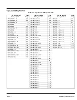


3-22 Receiving & Installation
MN718
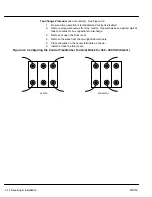
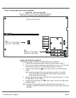
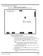
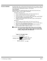
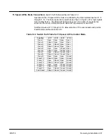
Size E Single Phase Power Installation
Figure 3-7 Jumper Configuration
Place JP1 on the High Voltage Circuit Board across pins 1 and 2.
JP1
1
JP2
J7
J8
J2
AC INPUT
CNTRL XFMR
400V PRI
DUAL 230V
F
ANS
SINGLE
230V F
ANS
CNTRL XFMR
460V PRI
1
High Voltage Circuit Board
(100 - 150HP E Size)
8470
JP1
Pins 1 & 2 = Single Phase
Pins 2 & 3 = Three Phase
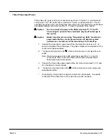
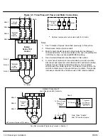
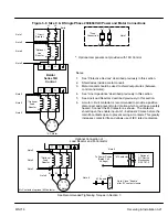
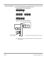
Power and Control Connections
The single phase power and motor connections are shown in Figure 3-8.
1.
Connect the incoming power wires to Main Circuit Terminals L1 and L2.
2.
Place a jumper across control power input terminals L2 and L3. Use the same
size wire for the jumper as the incoming power wires on L1 and L2.
3.
Connect earth ground to the “ ” of the control. Be sure to comply with local
codes.
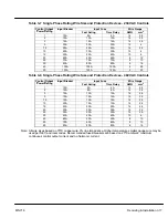
Note: Use same gauge wire for earth ground as is used for L1, L2 and L3
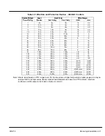
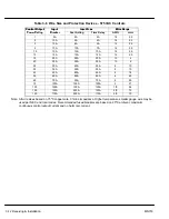
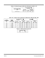
connections. Refer to the Wire Size and Protection Devices tables
shown previously in this section.
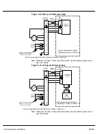
4.
Connect the three phase power leads of the AC motor to terminals T1, T2, and
T3 of the Main Circuit Terminals.
5.
Connect motor ground wire to the “ ” of the control. Be sure to comply with all
applicable codes.
Note: In steps 3 and 5 grounding by using conduit or panel connection is not
adequate. A separate conductor of the proper size must be used as a ground
conductor.
Summary of Contents for 18H Series
Page 1: ...SERIES 18H AC Flux Vector Control Installation Operating Manual 9 97 MN718 VECTOR DRIVE ...
Page 105: ...Section 1 General Information 5 18 Troubleshooting MN718 ...
Page 109: ...Section 1 General Information 6 4 Manual Tuning the Series 18H Control MN718 ...
Page 144: ...Appendix C Appendix C 1 MN718 ...