background image

© Siemens plc 1999

G85139-H1750-U049-C1

19/08/99

Contents

SAFETY INSTRUCTIONS..................................................... 3
1.  OVERVIEW....................................................................... 4
2.  INSTALLATION.............................................................. 10
3.  FRONT PANEL CONTROLS & BASIC OPERATION ... 18
4.  OPERATING MODES..................................................... 21
5.  SYSTEM PARAMETERS ............................................... 24
6.  FAULT CODES............................................................... 39
7.  SPECIFICATIONS .......................................................... 40
8.  SUPPLEMENTARY INFORMATION ............................. 43
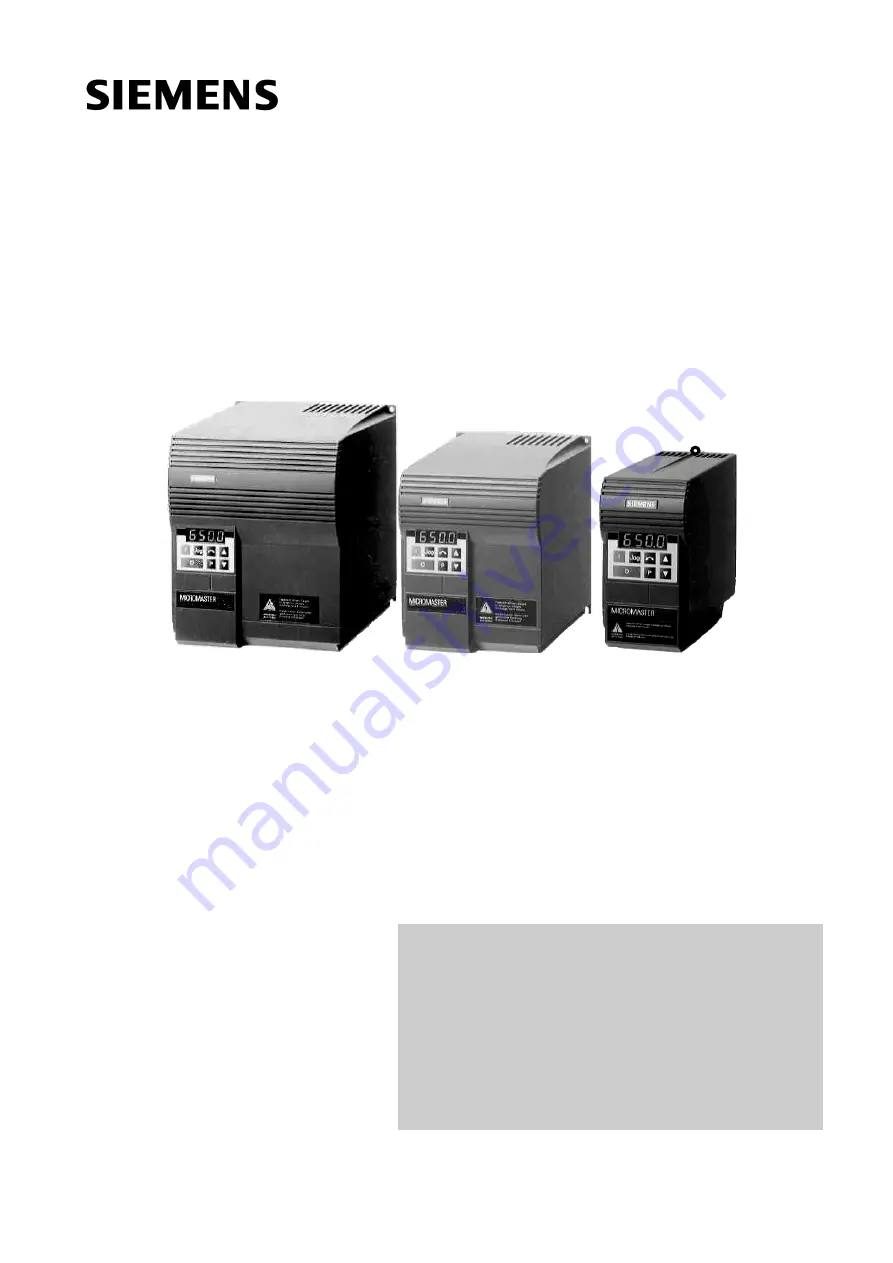
MICROMASTER

Operating Instructions

Summary of Contents for Micromaster 15-8DB50

Page 1: ...Contents SAFETY INSTRUCTIONS 3 1 OVERVIEW 4 2 INSTALLATION 10 3 FRONT PANEL CONTROLS BASIC OPERATION 18 4 OPERATING MODES 21 5 SYSTEM PARAMETERS 24 6 FAULT CODES 39 7 SPECIFICATIONS 40 8 SUPPLEMENTARY INFORMATION 43 MICROMASTER Operating Instructions ...

Page 2: ...me Size C 14 2 2 4 Control Connections 16 2 2 5 External Motor Thermal Overload Protection 17 2 2 6 Block Diagram 17 3 Front Panel Controls Basic Operation 18 3 1 Front Panel Controls 18 3 2 Basic Operation 19 3 2 1 General 19 3 2 2 Initial Testing 19 3 2 3 Basic Operation 10 Step Guide 20 4 Operating Modes 21 4 1 Digital Control 21 4 2 Analogue Control 21 4 3 Stopping the Motor 22 4 4 If the Moto...

Page 3: ...his applies to units at software issue P922 3 06 or greater only This equipment is suitable for use in a circuit capable of delivering not more than 100 000 symmetrical amperes rms for a maximum voltage of 230 460V when protected by a time delay fuse See Section 7 This equipment must not be used as an emergency stop mechanism see EN 60204 9 2 5 4 If motor thermal protection is required then an ext...

Page 4: ...verters A comprehensive range of parameters is provided to enable the inverters to be configured for use in almost any application Membrane type front panel controls for simple operation Built in non volatile memory for storing parameter settings Factory default parameter settings pre programmed for European and North American requirements Output frequency and hence motor speed can be controlled b...

Page 5: ...er hazards e g do not install the inverter beneath pipes that are subject to condensation Avoid installing the inverter where excessive humidity and condensation may occur Mount the inverter vertically to ensure optimum cooling Additional ventilation may be required for horizontal mounting Ensure that the inverter s air vents are not obstructed including the air vent at the front of the unit which...

Page 6: ...nnection PE on the associated inverter 2 Wherever possible use screened leads for connections to the control circuitry Terminate the ends of the cable neatly ensuring that unscreened wires are as short as possible Use cable glands whenever possible 3 Separate the control cables from the power connections as much as possible using separate trunking etc If control and power cables cross arrange the ...

Page 7: ...inimise effects of EMI MICROMASTER FSB MAINS POWER INPUT METAL BACK PLATE FOOTPRINT FILTER CONTROL CABLE CONTROL CABLE Fix motor and control cable screens securely to metal back plate using suitable clips MAINS POWER INPUT METAL BACK PLATE FOOTPRINT FILTER CONTROL CABLE Fix motor and control cable screen securely to metal back plate using suitable clips EARTH BRAID EARTH BRAID ...

Page 8: ...1 Siemens plc 1999 19 08 99 8 Figure 1 2 3 Wiring guidelines to minimise effects of EMI MICROMASTER FSC MAINS POWER INPUT FOOTPRINT FILTER METAL BACK PLATE Fix motor and control cable screen securely to metal back plate using suitable clips ...

Page 9: ...ry to reform the capacitors in the inverter if the unit has been stored for a prolonged period Period of storage 1 year old or less No reforming is required 1 2 years old Apply power to the inverter one hour before giving the run command Preparation time 1 Hour 2 3 years old Use a variable AC supply Apply 25 of input voltage for 30 minutes Increase volts to 50 for a further 30 minutes Increase vol...

Page 10: ...fety regulations regarding work on dangerous voltage installations e g VDE as well as the relevant regulations regarding the correct use of tools and personal protective gear The mains input and motor terminals can carry dangerous voltages even if the inverter is inoperative Use insulated screwdrivers only on these terminal blocks DIN Rail Depth D W H2 H1 F 4 5 mm Depth D W H H1 4 8 mm B 5 6 mm C ...

Page 11: ...ation test equipment must not be used on cables connected to the inverter Use screened cable for the control lead Use Class 1 60 75 o C copper wire only for UL compliance Tightening torque for the power mains input and motor terminals is 1 1 Nm To tighten up the power motor terminal screws use a 4 5 mm cross tip screwdriver 2 2 1 Power and Motor Connections Frame Size A Ensure that the power sourc...

Page 12: ...INSTALLATION CONTACTOR FILTER L3 MICROMASTER L1 L2 L3 L2 L1 P PE PE W W V V U U MOTOR MOTOR THREE PHASE SINGLE PHASE Figure 2 2 1 Power Connections Asynchronous and synchronous motors can be connected to the MICROMASTER inverters either individually or in parallel Note If a synchronous motor is connected to the inverter the motor current may be two and a half to three times greater than that expec...

Page 13: ...ease catches D and E to release the gland plate and then remove the metal gland plate from the inverter 1 Insert the blade of a small screwdriver into slot A in the front of the inverter and press in the direction of the arrow At the same time press down on tab B at the side of the access panel 2 This will release the access panel which will then swing down on its rear mounted hinges Note The acce...

Page 14: ...s U V W and the earth PE shown in Figure 2 2 2 and torque down the screws Note For operation with cables longer than 25m see section 1 3 14 If required secure Faston connectors to the braking resistor leads and fit the connectors to the B DC and B terminals under the inverter 15 Connect the control leads as shown in Figures 2 2 4 and 2 2 6 Section 2 2 4 and 2 2 6 2 2 3 Power and Motor Connections ...

Page 15: ...ize C A Fan housing opening tab B C Gland plate release tabs D Control cable input E Mains cable input F Motor cable input G Braking resistor DC link cable input H J H Fan connector J Fan Housing removal tab To remove fan housing and fan disconnect fan connector H release tab J in direction shown and remove fan and housing in same direction ...

Page 16: ...ay normallyopen max 0 4A 110VAC 1A 30VDC resistiverating Digital Inputs 7 5 33V max 5mA Power Supply for PI Feedback Transducer or other load 15V max 50mA P10 0V AIN AIN P15 DIN1 DIN2 DIN3 RL1B NO RL1C COM 0V Control Terminal Block Insert small blade screwdriver max 3 5 mm as shown while insertingcontrol wirefrombelow Front Panel RS485D type N 0V 5V max 250mA P 6 1 5 9 Figure 2 2 4 Control Connect...

Page 17: ... a PTC temperature sensor must be fitted to the motor and connected to the inverter control terminals as shown in Figure 2 2 5 Note To enable the trip function set parameter P051 P052 or P053 19 MOTOR PTC 1kΩ Ω Ω Ω 8 9 7 Inverter Control Terminals Figure 2 2 5 Motor Overload PTC Connection 2 2 6 Block Diagram P Jog M PE U V W 3 CPU AD SI 2 3 4 5 6 10 11 PE 1 3 AC 230 V 3 AC 380 500 V L L1 N L2 or ...

Page 18: ...d run at the preset jog frequency The inverter stops as soon as the button is released Pressing this button while the inverter is running has no effect Disabled if P123 0 Press to start the inverter Disabled if P121 0 Press to stop the inverter Press once for an OFF1 see section 4 3 Press twice or hold down for an OFF2 see section 4 3 to immediately remove voltage from the motor allowing the motor...

Page 19: ...P081 to P085 see Figure 3 2 1 Note Access to these parameters is not possible unless P009 has been set to 002 or 003 3 Mot IEC 56 IM B3 cosϕ 0 81 cosϕ 0 81 1LA5053 2AA20 Nr E D510 3053 IP54 Rot KL 16 I Cl F 12 022 60 Hz 440 V Y 0 34 A 0 14 kW 3310 min 220 380 V Y 0 12 2745 VDE 0530 S F 1 15 min P081 P084 P083 P082 P085 0 61 0 35 A 50 Hz kW Figure 3 2 1 Typical Motor Rating Plate Example Note Ensur...

Page 20: ...ry default setting 5 Press the button to set the desired frequency setpoint e g 35 Hz 6 Press P to lock the setting into memory 7 Press the button to return to P000 8 Press P to exit the parameterisation procedure The display will alternate between the current frequency and the requested frequency setpoint 9 Start the inverter by pressing the RUN button The motor shaft will start to turn and the d...

Page 21: ...e frequency set by P005 4 2 Analogue Control For a basic startup configuration using analogue voltage control proceed as follows 1 Connect control terminal 5 to terminal 8 via a simple on off switch This sets up the motor for clockwise rotation default 2 Connect a 4 7 kΩ potentiometer to the control terminals as shown in Figure 2 2 4 or connect pin 2 0V to pin 4 and a 0 10 V signal between pin 2 0...

Page 22: ...ameters have been changed accidentally reset the inverter to the factory default parameter values by setting parameter P944 to 001 and then pressing P 4 5 Local and Remote Control The inverter can be controlled either locally default or remotely via a USS data line connected to the RS485 D type connector on the front panel Refer to parameter P910 in Section 5 for the available remote control optio...

Page 23: ... P206 Scaling P211 P212 Sample Interval P205 Transducer Type P208 Closed Loop Control on off P201 MICROMASTER Figure 4 6 1 4 6 2 Hardware Setup Connect the outputs from the external feedback transducer to control terminals 3 and 4 This analogue input accepts a 0 2 10 V signal has 10 bit resolution and permits a differential floating voltage Ensure that the values of parameters P023 and P024 are se...

Page 24: ...rs necessary for your application have been programmed Note In the following parameter table Indicates parameters that can be changed during operation Indicates that the value of this factory setting depends on the rating of the inverter Increased Parameter Resolution To increase the resolution to 0 01 when changing frequency parameters instead of pressing P momentarily to return to the parameter ...

Page 25: ... 2 Motor current A 3 DC link voltage V 4 Not used 5 Motor RPM 6 USS status see section 8 2 7 Closed loop control setpoint of full scale 8 Output voltage P002 Ramp up time seconds 0 650 0 10 0 This is the time taken for the motor to accelerate from standstill to the maximum frequency as set in P013 Setting the ramp up time too short can cause the inverter to trip fault code F002 overcurrent Frequen...

Page 26: ... by setting any two of binary inputs P051 P053 to values of 11 and 12 1 Analogue Control via analogue input signal 2 Fixed frequency or motor potentiometer Fixed frequency is only selected if the value of at least one binary input P051 P053 6 17 or 18 Notes 1 If P006 1 and the inverter is set up for remote control operation the analogue inputs remain active 2 Motor potentiometer setpoints via digi...

Page 27: ...g restart the inverter homes in on the motor s speed and runs it up from that speed to the setpoint Note If the motor has stopped or is rotating slowly some rocking may occur as the inverter senses the direction of rotation prior to restarting See also P020 0 Normal restart 1 Flying restart after power up fault or OFF2 if P018 1 2 Flying restart every time useful in circumstances where the motor c...

Page 28: ...l fixed setpoint by analogue input P023 in the range 0 100 Note By selecting a combination of reversed negative fixed frequency settings and analogue setpoint addition it is possible to configure the inverter for centre zero operation with a 5 V supply or a 0 10 V potentiometer so that the output frequency can be 0 Hz at any position including the centre position P027 Skip frequency 2 Hz 0 400 00 ...

Page 29: ...rameter instead of the normal Ramp down time set by P003 P041 Fixed frequency 1 Hz 0 400 00 5 00 Valid if P006 2 and P053 6 or 18 or P053 55 17 P042 Fixed frequency 2 Hz 0 400 00 10 00 Valid if P006 2 and P052 6 or 18 or P053 55 17 P043 Fixed frequency 3 Hz 0 400 00 15 00 Valid if P006 2 and P051 6 or 18 or P053 55 17 P044 Fixed frequency 4 Hz 0 400 00 20 00 Valid if P006 2 and P051 P052 P053 17 P...

Page 30: ...logue input setpoint is 0 0 Hz Disable the ability to change parameters Enable dc brake Use jog ramp times instead of normal ramp times Binary fixed frequency control fixed frequencies 1 7 As 6 but RUN signal not required External trip PTC Function low state Off Off Normal OFF2 OFF3 Off Off Off Local Off Off Off Analogue on enabled Off Normal Off Off Yes F012 Function high state On right On left R...

Page 31: ...h off see parameter P931 3 Active low relay OPEN Active high relay CLOSED Note If the external brake function is used P061 or P062 4 and additional slip compensation is used P071 0 minimum frequency must be less than 5 Hz P012 5 00 otherwise the inverter may not switch off Warning Relay operation is not defined during parameter changes and may change unpredictably Ensure any equipment connected to...

Page 32: ...parameter is used when P061 9 The relay switches on when the motor current is greater than the value of P065 and switches off when the current falls to 90 of the value of P065 hysteresis P066 Compound braking 0 1 1 0 Off 1 On Permits faster ramp down times and enhances stopping capability P073 DC injection braking 0 150 0 This stops the motor by applying a DC current This causes heat to be generat...

Page 33: ...ad of reducing the motor torque speed 6 As P074 2 but the inverter trips F074 instead of reducing the motor torque speed 7 As P074 3 but the inverter trips F074 instead of reducing the motor torque speed Note I2t motor protection is not recommended where the motor is less than half the power rating of the inverter WARNING Where motor thermal protection is required an external PTC must be used P076...

Page 34: ...he available torque for low frequency operation 100 setting will produce rated motor current at low frequencies WARNING If P078 is set too high overheating of the motor and or an overcurrent trip F002 can occur P079 Starting boost 0 250 0 For drives which require a high initial starting torque it is possible to set an additional current added to the setting in P078 during ramping This is only effe...

Page 35: ...tor connected The measurement should be made at the inverter output terminals with power off Note If the value of P089 is too high then an overcurrent trip F002 may occur P091 Serial link slave address 0 30 0 Up to 31 inverters can be connected via the serial link and controlled by a computer or PLC using the USS protocol This parameter sets a unique address for the inverter P092 Serial link baud ...

Page 36: ... MM220 2 18 MM300 2 19 MM400 2 20 MM37 3 21 MM55 3 22 MM75 3 23 MM110 3 24 MM150 3 25 MM220 3 26 MM300 3 27 MM400 3 28 MM550 3 29 MM750 3 P121 Enable disable RUN button 0 1 1 0 RUN button disabled 1 RUN button enabled only possible if P007 1 P122 Enable disable FORWARD REVERSE button 0 1 1 0 FORWARD REVERSE button disabled 1 FORWARD REVERSE button enabled only possible if P007 1 P123 Enable disabl...

Page 37: ... 0 00 Integral gain 0 01 corresponds to the longest integral action time P205 Sample interval x 25 ms 1 2400 1 Sampling interval of feedback sensor The integral response rate is slowed down by this factor P206 Transducer filtering 0 255 0 0 Filter off 1 255 Low pass filtering applied to sensor P207 Integral capture range 0 100 100 Percentage error above which integral term is reset to zero P208 Tr...

Page 38: ...ded fault code see section 6 is stored in this parameter This parameter can be cleared using the and buttons P931 Most recent warning type 0 9999 The last recorded warning is stored in this parameter until power is removed from the inverter 002 Current limit active 003 Voltage limit active 005 Inverter over temperature Internal PTC 006 Motor over temperature 018 Auto restart after fault Warning in...

Page 39: ...09 to 0000 before power down F011 Internal interface fault Switch off power and switch on again F012 External trip PTC Check if motor is overloaded F013 Programme fault Switch off power and switch on again F030 PROFIBUS link failure Check the integrity of the link F031 Option module to link failure Check the integrity of the link F033 PROFIBUS configuration error Check the PROFIBUS configuration F...

Page 40: ... A 2 6 A 3 5 A 4 8 A 6 6A 9 0 A 11 8 A 15 9 A Output current max continuous 0 9 A 1 7 A 2 3 A 3 0 A 3 9 A 5 5 A 7 4 A 10 4 A 13 6 A 17 5 A Input current I rms 1 AC 3 AC 1 8 1 1 A 3 2 1 9 A 4 6 2 7 A 6 2 3 6 A 8 2 4 7 A 11 0 6 4A 14 4 8 3A 20 2 11 7A 28 3 16 3A 21 1 A Recommended mains fuse b 10 A 16 A 20 A 25 A Recommended lead Input 1 0 mm2 1 5 mm2 2 5 mm2 4 0 mm2 cross section min Output 1 0 mm2...

Page 41: ...5 9 5 3 A 7 7 6 9 A 10 2 9 1A 13 2 11 8A 17 0 15 2A Input current I rms 8 8 A 11 1 A 13 6 A 17 1 A 22 1 A Recommended mains fuse 16 A 20 A 25 A Recommended lead Input 1 5 mm2 2 5 mm2 4 0 mm2 cross section min Output 1 5 mm2 2 5 mm2 Dimensions mm w x h x d 149 x 184 x 172 185 x 215 x 195 Weight kg lb 2 4 5 3 4 8 10 5 Integrated Class B may be achieved by adding a Class B footprint filter to an unfi...

Page 42: ...xternal inductive loads must be suppressed in an appropriate manner see section 1 2 4 Interface RS485 Inverter efficiency 97 typically Operating temperature 0 o C to 50 o C Storage transport temperature 40 o C to 70 o C Ventilation Fan cooled Software Controlled Humidity 95 non condensing Installation height above sea level 1000 m Note If the Inverter is to be installed at an altitude 1000m derati...

Page 43: ...n addition to analogue setpoint Use of analogue setpoint at maximum 10 Hz Ramp times to remain the same Parameter adjustments P009 2 all parameters can be altered P013 75 maximum motor frequency in Hz P006 2 setpoint via motor potentiometer or fixed setpoint P024 1 analogue setpoint is added P022 10 maximum analogue setpoint at 10 V 10 Hz 8 2 USS Status Codes The following list gives the meaning o...

Page 44: ... Examination Certificate This approach is only applicable to radio communication transmitting apparatus The MICROMASTER units do not have an intrinsic function until connected with other components e g a motor Therefore the basic units are not allowed to be CE marked for compliance with the EMC directive However full details are provided below of the EMC performance characteristics of the products...

Page 45: ...ency Electromagnetic Field amplitude modulated ENV 50 140 80 1000 MHz 10 V m 80 AM power and signal lines Radio frequency Electromagnetic Field pulse modulated ENV 50 204 900 MHz 10 V m 50 duty cycle 200 Hz repetition rate Class 3 Filtered for residential commercial and light industry This level of performance will allow the manufacturer assembler to self certify compliance of their apparatus with...

Page 46: ...6SE3290 0DA87 0FB1 EN 55011 EN 55022 MM220 3 MM300 3 A B 6SE3290 0DB87 0FA3 6SE3290 0DB87 0FB3 EN 55011 EN 55022 MM400 3 MM750 3 A B 6SE3290 0DC87 0FA4 6SE3290 0DC87 0FB4 EN 55011 EN 55022 Class B filters are for use with 1 3 AC 230V unfiltered units Note Maximum mains supply voltage when filters are fitted is 460V 8 4 Environmental Aspects Transport and Storage Protect the inverter against physic...

Page 47: ... 00 P044 20 00 P045 0 P046 25 00 P047 30 00 P048 35 00 P050 0 P051 1 P052 2 P053 6 P056 0 P061 6 P062 0 P063 1 0 Parameter Your setting Default P064 1 0 P065 1 0 P066 1 P073 0 P074 1 P076 0 4 P077 1 P078 100 P079 0 P081 50 00 P082 P083 P084 P085 P089 P091 0 P092 6 P093 0 P094 50 00 P095 0 P099 0 P101 0 P111 P112 P113 P121 1 P122 1 P123 1 P124 1 P125 1 P128 120 P129 P131 P132 P134 P135 P137 P140 P1...

Page 48: ...h 3269 D 91050 Erlangen Siemens plc Automation Drives Standard Drives Division Siemens House Varey Road Congleton CW12 1PH Änderungen vorbehalten Specification subject to change without prior notice G85139 H1750 U049 C1 H1750 U049 C1 Siemens plc 1999 Printed in England Bestell Nr 6SE9286 4AA86 6SE9286 4AA86 ...

Reviews: