background image

BLACK BOX

®

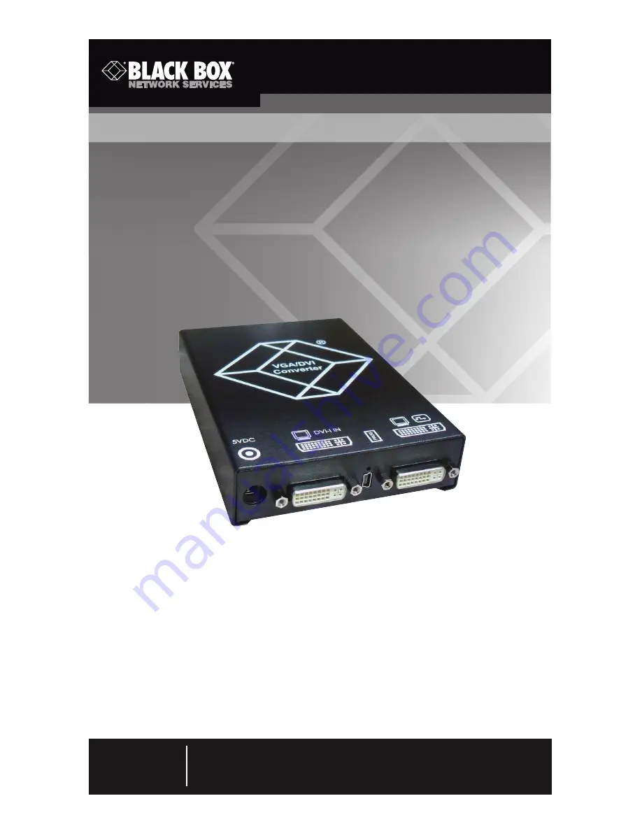
Convert and output video signals of one or more 

video sources (computer, CPU, camera, or DVD 

player) in DVI-D format.

Media/DVI Converters

Order toll-free in the U.S.: Call 877-877-BBOX (outside U.S. call 724-746-5500)
FREE technical support 24 hours a day, 7 days a week: Call 724-746-5500 or fax  
724-746-0746  •  Mailing address: Black Box Corporation, 1000 Park Drive, Lawrence, 
PA 15055-1018  •  Web site: www.blackbox.com  •  E-mail: [email protected]

Customer 

Support 

Information

ACS411A-R2 

ACS413A 

ACS412A 

ACS414A

Summary of Contents for ACS411A-R2

Page 1: ...toll free in the U S Call 877 877 BBOX outside U S call 724 746 5500 FREE technical support 24 hours a day 7 days a week Call 724 746 5500 or fax 724 746 0746 Mailing address Black Box Corporation 1000 Park Drive Lawrence PA 15055 1018 Web site www blackbox com E mail info blackbox com Customer Support Information ACS411A R2 ACS413A ACS412A ACS414A ...

Page 2: ...n this Manual Black Box and the Double Diamond logo are registered trademarks of BB Technologies Inc IBM is a registered trademark of International Business Machines Corporation Any other trademarks mentioned in this manual are acknowledged to be the property of the trademark owners ...

Page 3: ...uired to take whatever measures may be necessary to correct the interference Changes or modifications not expressly approved by the party responsible for compliance could void the user s authority to operate the equipment This digital apparatus does not exceed the Class A limits for radio noise emis sion from digital apparatus set out in the Radio Interference Regulation of Industry Canada Le prés...

Page 4: ...ra o superficie similar puede bloquea la ventilación no se debe colocar en libreros o gabinetes que impidan el flujo de aire por los orificios de ventilación 10 El equipo eléctrico deber ser situado fuera del alcance de fuentes de calor como radiadores registros de calor estufas u otros aparatos incluyendo amplificadores que producen calor 11 El aparato eléctrico deberá ser connectado a una fuente...

Page 5: ...o sean derramados sobre la cubierta u orificios de ventilación 18 Servicio por personal calificado deberá ser provisto cuando A El cable de poder o el contacto ha sido dañado u B Objectos han caído o líquido ha sido derramado dentro del aparato o C El aparato ha sido expuesto a la lluvia o D El aparato parece no operar normalmente o muestra un cambio en su desempeño o E El aparato ha sido tirado o...

Page 6: ...lace them in an enclosed space without any airflow Do not place the power supply directly on top of the device Do not obscure ventilation holes Only use power supplies originally supplied with the product or manufacturer approved replacements Do not use a power supply if it appears to be defective or has a damaged case Connect all power supplies to grounded outlets In each case make sure that the ...

Page 7: ...nnector 21 2 Overview 22 2 1 Introduction 22 2 2 Available Products 23 2 3 Upgrade Kits 23 2 4 What s Included 23 2 5 Hardware Description 26 2 5 1 ACS411A R2 26 2 5 2 ACS412A 27 2 5 3 ACS413A 28 2 5 4 ACS414A 29 2 6 Status LEDs 30 3 Installation 31 3 1 System Setup 31 3 2 Example Applications 31 4 Configuration 33 4 1 Infrared Remote Control 33 4 2 On Screen Display OSD 37 4 2 1 Main Menu Item Co...

Page 8: ...ngs 49 5 1 2 Input Settings 49 5 1 3 Picture Settings 50 5 2 Download of DDC Information 50 5 2 1 Download DDC Using the Infrared Remote Control 51 5 2 2 Download DDC Using the OSD 51 6 Troubleshooting 52 6 1 Blank Screen 52 6 2 Picture 53 6 3 General 54 6 4 Contacting Black Box 54 6 5 Shipping and Packaging 54 7 Glossary 55 ...

Page 9: ...DVI I connector 1 DVI D female 1 2 1 mm barrel connector 1 Mini USB connector PROG port ACS414A 5 BNC RGBHV inputs 1 VGA DVI I connector 1 DVI D female 1 2 1 mm barrel connector 1 Mini USB connector PROG port Indicators 1 multicolor Status LED Temperature Tolerance Operating 41 to 113 F 5 to 45 C Storage 13 to 140 F 25 to 60 C Relative Humidity Maximum 80 noncondensing Power ACS411A R2 5 VDC exter...

Page 10: ...60 WF470 AS215 512 512 50 1 31 3 24 0 12 GEM 80 graph i 560 224 25 0 15 6 11 7 24 GEM 80 graph i 560 224 30 1 15 8 11 9 28 GEM 80 graph i 560 224 37 5 18 2 12 0 45 750b 560 248 41 6 26 0 20 0 8 GBE3977 80 x 48 560 288 50 0 15 6 13 0 9 DISET 80 x 25 560 288 50 0 15 6 12 2 19 DCS 560 560 288 50 0 15 7 11 4 44 MONA C 560 413 58 2 25 8 20 0 61 GEM 80 graph progr 560 448 50 1 31 3 23 5 64 GEM 80 graph ...

Page 11: ...39 3 32 4 37 VGA 640 400 55 9 24 6 20 9 49 OP 398 K 640 400 60 0 27 5 22 2 164 VGA 640 400 70 2 31 5 25 2 168 VGA 640 400 84 9 37 8 31 4 38 COROS LS C 640 405 59 1 25 4 21 7 40 COROS LS C 640 405 59 1 25 4 21 7 42 Prokon 1 640 432 53 8 25 5 23 1 48 Prokon 3 640 432 58 9 27 4 23 0 56 CP526 high res 640 468 60 0 30 0 26 2 57 CP528 high res 640 468 60 0 30 9 28 3 59 CP526 high res 640 468 50 0 31 2 2...

Page 12: ... NTSC Interlaced 720 240 30 1 15 8 13 6 11 PAL Interlaced 720 288 25 0 15 6 13 5 27 ABB DSAV110 720 336 50 1 17 9 15 6 29 Hercules Monochrom 720 350 49 7 18 4 16 2 72 XGA2 720 350 87 8 39 4 35 5 163 VGA 720 350 70 2 31 5 28 4 167 VGA 720 350 84 9 37 8 35 4 31 Custom 2 720 400 49 9 20 6 18 5 46 NEC 27 kHz 720 400 55 0 27 0 24 3 73 XGA2 720 400 87 8 39 4 35 5 165 VGA 720 400 70 2 31 5 28 4 169 VGA 7...

Page 13: ...A Standard 800 600 84 9 53 6 56 2 100 MAC Mode 832 624 75 0 49 5 55 4 101 MAC Mode 832 624 74 5 49 7 57 3 80 VESA Standard 960 600 60 1 37 4 46 0 77 768i 1024 384 43 0 35 5 44 9 78 768p 1024 768 86 8 35 5 44 9 98 VG901101 1024 768 59 9 48 3 64 9 99 MAC Mode 1024 768 59 9 48 7 63 9 112 VS910801 1024 768 70 0 56 4 74 9 113 IBM 1024 768 72 1 57 5 75 0 114 SUN Mode 1024 768 72 0 58 0 75 2 116 VESA Sta...

Page 14: ...0 0 15 6 26 0 50 1280i 1280 512 25 0 28 0 44 6 82 VESA CVT 16 9 1280 720 50 0 37 5 74 3 90 VESA CVT 16 9 1280 720 59 9 44 8 74 5 94 TV Mode 1280 768 60 0 47 7 80 1 97 TV Mode 1280 768 60 0 48 1 81 2 102 Beamer 16 10 1280 800 59 8 49 7 83 5 115 VESA Standard 1280 960 60 0 60 0 108 0 139 GTF 1280 960 72 0 72 1 124 6 143 DMT 127A 1280 960 75 0 75 0 126 0 148 GTF 1280 960 77 3 77 5 133 9 156 VESA Stan...

Page 15: ...5 8 27 1 109 TV Mode 16 10 1440 900 60 0 55 6 89 0 103 1200i 1600 600 40 0 50 0 108 0 110 TV Mode 16 9 1600 900 59 9 56 8 118 7 123 VESA Standard 1600 1024 60 2 63 8 136 8 142 VESA Standard 1600 1200 60 0 75 0 162 0 144 UXGA 1600 1200 50 1 75 0 138 0 145 UXGA rb 1600 1200 60 3 75 4 140 5 152 VESA Standard 1600 1200 65 0 81 3 175 6 157 VESA Standard 1600 1200 70 0 87 5 189 0 159 VESA Standard 1600 ...

Page 16: ... 1080 59 7 66 8 172 1 131 1080p 1920 1080 60 0 67 5 148 5 140 WUXGA 1920 1200 59 9 74 0 153 9 141 WUXGA 1920 1200 59 6 74 2 192 3 132 2048 1080 60 Hz 2048 1080 60 0 67 5 148 5 136 2048 1151 60 Hz 2048 1152 59 9 71 0 156 8 Table 1 2 Supported video modes for Component Composite Video S Video and SDI Description FBAS S Video Component HD SDI 480i 60 Hz X X X X 576i 50 Hz X X X X 480p 60 Hz X 576p 60...

Page 17: ...ata 0 2 T M D S data 2 10 T M D S data 1 18 T M D S data 0 3 T M D S data 2 GND 11 T M D S data 1 GND 19 T M D S data 0 GND 4 Not connected 12 Not connected 20 Not connected 5 Not connected 13 Not connected 21 Not connected 6 DDC Input SCL 14 5 VDC high impedance 22 T M D S clock GND 7 DDC Ouput SDA 15 GND 23 T M D S clock 8 Internal use 16 Hot plug recognition 24 T M D S clock C1 Internal use C3 ...

Page 18: ... D S data 2 10 T M D S data 1 18 T M D S data 0 3 T M D S data 2 GND 11 T M D S data 1 GND 19 T M D S data 0 GND 4 Not connected 12 Not connected 20 Not connected 5 Not connected 13 Not connected 21 Not connected 6 DDC Input SCL 14 5 VDC high impedance 22 T M D S clock GND 7 DDC Ouput SDA 15 GND 23 T M D S clock 8 Internal use 16 Hot plug recognition 24 T M D S clock C1 Internal use C3 Internal us...

Page 19: ...cations 1 3 3 RCA Cinch Connector Figure 1 3 RCA Cinch connector Table 1 5 RCA Cinch connector pinouts Pin Signal 1 GND 2 Data IN OUT 1 3 4 BNC SDI RGB Connector Figure 1 4 BNC connector Table 1 6 BNC SDI RGB connector pinouts Pin Signal 1 Data IN 2 GND ...

Page 20: ... S Video connector pinouts Pin Signal 1 GND Y 2 GND C 3 Luminance Y 4 Chrominance C 1 3 6 DB9 EGA Connector Figure 1 6 DB9 connector Table 1 8 DB9 EGA connector pinouts Pin EGA CGA MDA 1 GND GND GND 2 Red LSB 3 Red MSB Red 4 Green MSB Green 5 Blue MSB Blue 6 Green LSB Intensity Intensity 7 Blue LSB Video 8 H SYNC H SYNC H SYNC 9 V SYNC V SYNC V YNC ...

Page 21: ...Page 21 724 746 5500 blackbox com Chapter 1 Specifications 1 3 7 Power Supply Connector Figure 1 7 Table 1 9 Power Supply connector pinouts Pin Signal Inside VCC 5 VDC Outside GND ...

Page 22: ...le input signals The DVI Converter can be used as a scaler scaling video signals to a specific output format The input ports of the DVI Converter connect to the video source s for example computer CPU camera DVD player SPS control using the provided cables or other suitable video cables The DVI D monitor connects to the output Figure 2 1 shows the system overview Table 2 1 describes its components...

Page 23: ...ble 2 3 Upgrade kits Product Code Description ACS1009A RMK 19 1U rackmount kit used to mount up to four ACS411A R2 devices ACS2209A RMK 19 1U rackmount kit used to mount up to four ACS412A ACS413A or ACS414A devices ACS4001A DRM Mounting plate used to mount by screws snap on for ACS411A R2 DRMBACU S Mounting option to mount on DIN rail vertical mount 2 4 What s Included Your package should contain...

Page 24: ... under ACS411A R2 plus the following items EGA cable 6 ft 1 8 m 1 DB9 connector Figure 2 3 EGA cable Component video cable 1 5 m 3 RCA connectors Figure 2 4 Component video cable S Video 9 6 ft 3 m 1 4 pole mini DIN connector Figure 2 5 S Video cable ACS413A contains everything listed under ACS411A R2 plus the following items SDI cable 6 4 ft 2 m BNC connector Figure 2 6 SDI cable ...

Page 25: ...le 5 ft 1 5 m 3 RCA connectors Figure 2 7 Component video cable S Video 9 6 ft 3 0 m 1 4 pole mini DIN connector Figure 2 8 S Video cable ACS414A contains everything listed under ACS411A R2 plus the following items RGB cable 6 4 ft 2 m 5 BNC connectors Figure 2 9 RGB cable ...

Page 26: ...n 2 5 1 ACS411A R2 6 Rear view Front view Figure 2 10 Front and back views of the ACS411A R2 Table 2 4 ACS411A R2 components Number Component 1 Connect to 5 VDC power supply 2 Input DVI I VGA 3 Service port 4 IR receiver for remote control 5 Output DVI D 6 LED status indicator ...

Page 27: ...k views of the ACS412A Table 2 5 ACS412A components Number Component 1 Connect to 5 VDC power supply 2 Input DVI I VGA 3 Service port 4 IR receiver for remote control 5 Output DVI D 6 Input S Video Y C 7 Input FBAS 1 or YPbPr Pr 8 Input FBAS 2 or YPbPr Y 9 Input FBAS 3 or YPnPr Pb 10 Input EGA 11 LED status indicator ...

Page 28: ... the ACS413A Table 2 6 ACS413A components Number Component 1 Connect to 5 VDC power supply 2 Input DVI I VGA 3 Service port 4 IR receiver for remote control 5 Output DVI D 6 Input S Video Y C 7 Input FBAS 1 or YPbPr Pr 8 Input FBAS 2 or YPbPr Y 9 Input FBAS 3 or YPbPr Pb 10 Input FBAS 4 11 Input HD SDI 12 LED status indicator ...

Page 29: ...ront and back views of the ACS414A Table 2 7 ACS414A components Number Component 1 Connect to 5 VDC power supply 2 Input DVI I VGA 3 Service port 4 IR receiver for remote control 5 Output DVI D 6 Input RGB red 7 Input RGB green 8 Input RGB blue 9 Input H Compos Sync 10 Input V Sync 11 LED status indicator ...

Page 30: ...s on the ACS411A R2 and ACS412A ACS414A Table 2 8 LED 1 Connection and video status LED Color Description for the Input Description for the Output Red No input signal Monitor detected Dark Red Resolution not supported Monitor not detected Green Active video signal Monitor not detected Blue No input signal Monitor detected Violet Resolution not supported Monitor detected Turquoise Active video sign...

Page 31: ...irements see Chapter 1 Specifications 1 Switch off all devices 2 Connect the monitor to the Media DVI Converter 3 Connect the source for example computer video camera or control unit to the media converter with the included cables Make sure that the cables are not strained 4 Connect the included 5 VDC power supply to the media converter 5 Power up the system NOTE Power up the system devices in thi...

Page 32: ... 1 description Composite video Number Component 1 Source observation camera 2 Media DVI Converter 3 Monitor 1 2 3 Figure 3 2 Example application 2 video input S Video Table 3 2 Example application 2 description S Video Number Component 1 Source DVD player 2 Media DVI Converter 3 Monitor ...

Page 33: ...ared remote control Navigate through the OSD menu items Figure 4 1 Infrared remote control NOTE In the OSD only the navigation keys of the infrared remote control function Navigation keys include red function key 8 key EXIT key ESC key and cursor keys t u p q Table 4 1 Infrared IR remote control key functions Button Description Open OSD or select menu Open OSD or select menu Leave OSD ...

Page 34: ...tions Button Description Leave current menu and open upper menu level Navigate inside the OSD Select parameters with cursor keys t and u Read and use DDC of the connected monitor Adjust picture contrast brightness Reset the Media DVI Converter to factory default Reset picture contrast birghtness to factory default ...

Page 35: ...IR remote control key functions Button Description If more than one converter is used select a single device for OSD access If more than one converter is used select all devices for OSD access Select input signal VGA DVI or SDI Select input signal Y C S Video YPbPr Component Video RGB EGA ...

Page 36: ...Page 36 724 746 5500 blackbox com Chapter 4 Configuration Table 4 1 Continued Infrared IR remote control key functions Button Description Select input signal FBAS 1 3 Cinch or FBAS 4 BNC ...

Page 37: ...VI Converter via the on screen display OSD Figure 4 2 General Structure of the OSD The left column shows the range of the main menu the right column shows the current submenus with the respective configuration options The various configuration and setting options of the Media DVI Converter are described in Sections 4 2 1 4 2 5 ...

Page 38: ...ings screen Table 4 2 Color Settings screen functions Menu Item Description Brightness Adjust brightness of the picture Contrast Adjust contrast of the picture Hue Change and adjust hue of the picture only selectable in case of video input signals Saturation Adjust saturation of the picture only selectable in case of video input signals Sharpness Adjust sharpness of the picture Color Open submenu ...

Page 39: ...ettings submenu screen Table 4 3 Color Settings submenu screen functions Menu Item Description Auto Color Adjust color values automatically Color Temperature Adjust color temperature of the picture RGB Activate the use of the standard RGB color range color optimization for tube monitors Red Adjust red color range Green Adjust green color range Blue Adjust blue color range ...

Page 40: ...DVI Converter Figure 4 5 Picture Settings screen Table 4 4 Picture Settings screen functions Menu Item Description Auto Configuration Configure picture settings automatically VGA RGB EGA input only Phase Adjust pixel phase that is the best position for the analog digital conversion within one pixel VGA RGB EGA input only Example of a wrong pixel phase ...

Page 41: ...lock shows the maximum number of the pixels that are can be displayed horizontally Even non visible and inactive pixels are included VGA RGB EGA input only Example of a wrong pixel clock Width Adjust width of the picture with the number of pixels Height Adjust height of the picture with the number of pixels Display Control Open Display Control submenu see the next page ...

Page 42: ...lay Control submenu screen functions Menu Item Description Display Image Select display optiion Auto Scale picture automatically to the maximum value Aspect Adjust aspect ratio manually 1 1 Show picture in original size with a black border Aspect Ratio Select aspect ratio Auto 4 3 14 9 16 9 or 16 9 only if Display Image is set to Aspect Ratio Zoom Zoom picture and determine position of enlargement...

Page 43: ... Select Composite channel For EGA input Select EGA CGA or MDA input signal Select Resolution Select video mode compatible to input signal see Chapter 1 Table 1 1 for supported video modes Save settings by leaving the menu monitor goes blank for a short time Sync Options Select type of synchronization of the RGB signal The type depends on the incoming RGB signal Auto automatic adjustment Composite ...

Page 44: ...C at the output Select Select from predefined output 1 1 Use input resolution as output resolution Resolution If Output is set to Select Select from predefined output resolutions A higher resolution can be selected at any time If you select a lower resolution the number of output pixels needs to comply with the following rule Horizontally At least 50 Vertically At least 33 Display Position Adjust ...

Page 45: ... described after the DDC submenu in this manual Device Address Assign device ID The device ID clearly identifies the device for the infrared remote control so that settings can be made for a specific device only Manage Settings Write the existing device settings on the internal memory of the media converter Save These settings can be loaded again if required Load for example after a firmware upgra...

Page 46: ...he monitor DDC as the device DDC and save it as DVI or VGA DDC Change DDC Save the device DDC as DVI or VGA DDC Factory DDC Use the default DDC VGA2DVI as the device DDC MON Display name and type of the monitor DDC DEV Display name and type of the device s DDC that is provided at the DVI I input by the media converter NOTE When saving the DDC as DVI or VGA DDC the selected type of the DDC must mat...

Page 47: ...laneous submenu options Menu Item Description Auto Adjust Activate or deactivate the automatic configuration of the picture settings after changing the video mode Refresh Rate Change refresh rate if the output is set to DDC Video Processing Not used VBI Processing Not used OSD Configuration Configure OSD display on the screen Factory Reset Reset device to factory default confirmation dialog ...

Page 48: ...Figure 4 12 OSD Configuration menu Table 4 11 OSD Configuration submenu options Menu Item Description OSD Timer Activate and select the time of inactivity after which OSD is closed automatically OSD Position Adjust vertical and horizontal OSD position on screen OSD Transparency Adjust OSD transparency OSD Zoom Activate scaling of OSD display ...

Page 49: ...oblems optimizing picture settings contact Black Box Technical Support at 724 746 5500 or info blackbox com 5 1 1 Optimization of Output Settings 1 If you have an analog input signal display a picture with as much detail as possible on your graphic source for example a text with black letters on a white ground or vice versa 2 Open the OSD with the infrared remote control 3 Select Output Settings i...

Page 50: ...l not satisfying after the automatic picture adjustment you can adjust clock and phase manually 1 Select Picture Settings in the main menu 2 Modify the values in the menu items Clock and Phase until all failures have disappeared 3 If the picture is displaced Select the menu item Display Position in the main menu item Output Settings and position the picture in the upper left corner of the monitor ...

Page 51: ...dia converter in the selected format The source computer CPU can read the DDC information of the monitor and display the available video resolutions 5 2 2 Download DDC Using OSD 1 Open the OSD with the infrared remote control 2 Select General Settings in the main menu see Section 4 2 5 3 Select the menu item Read DDC in the submenu DDC 4 Save the DDC as DVI or VGA DDC matching the input video sign...

Page 52: ...th and quality of the DVI D cable to monitor tighten cable thumbscrews Problem Status LED is dark red Possible Cause 1 No monitor is detected Solution 1 Check the connection length and quality of the DVI D cable to monitor tighten cable thumbscrews Possible Cause 2 Resolution on the device side is not supported Solution 2 Contact Black Box Technical Support at 724 746 5500 or info blackbox com we ...

Page 53: ...he parameters for the picture settings manually for example phase and clock see Section 4 2 2 Problem Parts of the picture are missing Possible Cause Wrong setting of picture size Possible Solution Optimize picture settings see Section 5 1 Problem Horizontal picture jitter Possible Cause Wrong settings of phase and clock Possible Solution Readjust phase and clock manually see Section 4 2 2 Problem...

Page 54: ...r info blackbox com Before you do make a record of the history of the problem We will be able to provide more efficient and accurate assistance if you have a complete description including the nature and duration of the problem when the problem occurs the components involved in the problem any particular application that when used appears to create the problem or make it worse 6 5 Shipping and Pac...

Page 55: ...extender to connect to a source computer CPU DDC The Display Data Channel DDC is a serial communication interface between a monitor and a source computer CPU It enables data exchange via monitor cable and an automatic installation and configuration of a monitor driver by the operating system Dual Access A system to operate a source computer CPU from two consoles Dual Head A system with two video c...

Page 56: ... with one video connection Single Link A DVI D interface for resolutions up to 1920 x 1200 by signal transmission of up to 165 MPixels s 24 bit Alternative frequencies are Full HD 1080p 2K HD 2048 x 1080 and 2048 x 1152 Single mode 9 µ single mode fiber cable S Video Y C The S Video Y C is a video format transmitting luminance and chrominance signals separately It has a higher quality standard tha...

Page 57: ...Page 57 724 746 5500 blackbox com NOTES ...

Page 58: ...Page 58 724 746 5500 blackbox com NOTES ...

Page 59: ...Page 59 724 746 5500 blackbox com NOTES ...

Page 60: ...ACS411A R2 version 2 About Black Box Black Box provides an extensive range of networking and infrastructure products You ll find everything from cabinets and racks and power and surge protection products to media converters and Ethernet switches all supported by free live 24 7 Tech support available in 30 seconds or less Copyright 2012 Black Box Corporation All rights reserved ...

Reviews: