


Section 1
General Information
Receiving & Installation 3-31
MN718
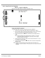
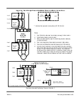
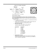
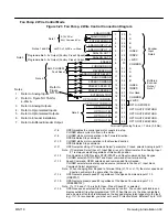
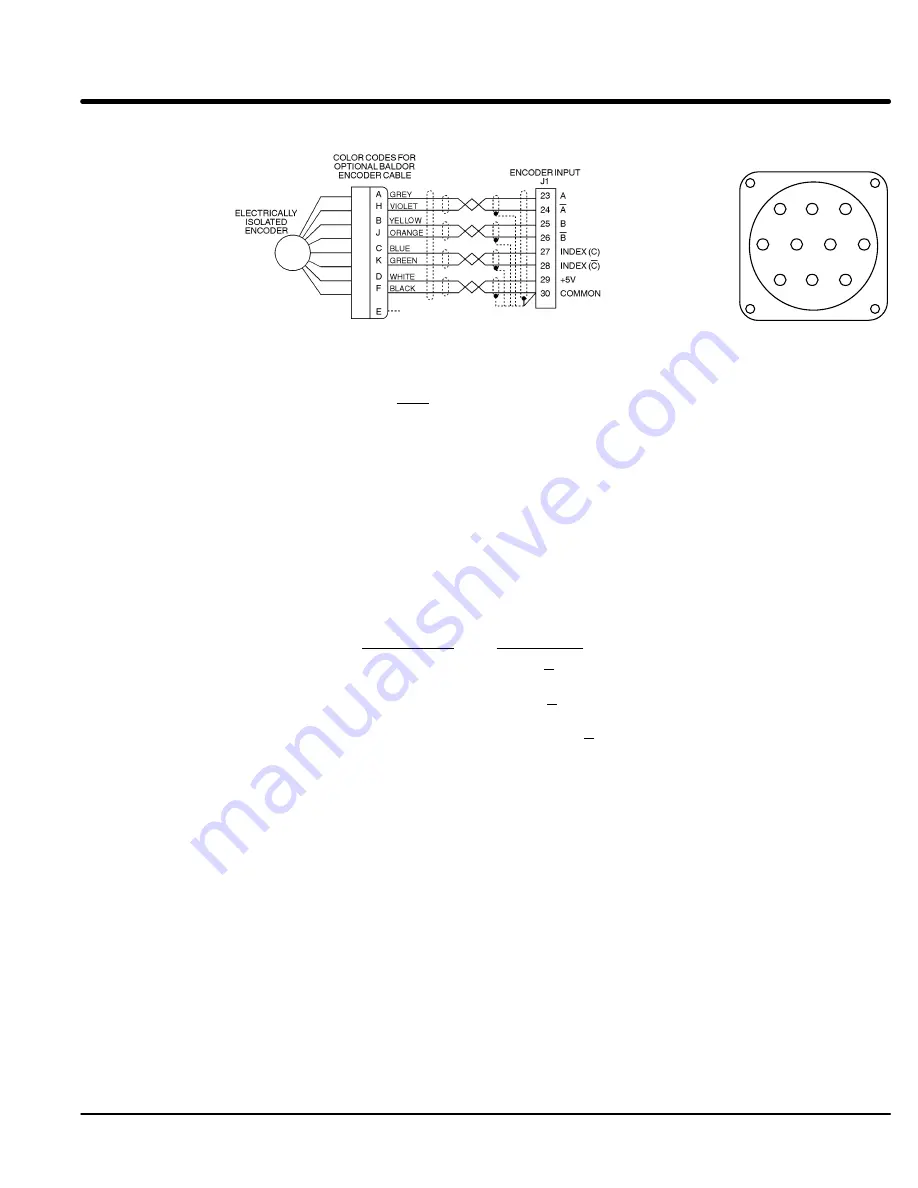
Figure 3-17 Encoder Connections
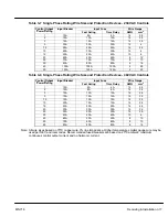
Terminal Tightening Torque = 7 Lb-in (0.8 Nm).
No Connection
A
B
K
H
G
J
C
F
E
D
Encoder Cable Connection
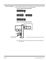
Encoder cable must be separated by at least 3” (76mm) from parallel runs of power
wires. Encoder cables that cross power wires must cross at a 90
°
angle only. Encoder
wires must be #22 AWG (0.34mm
2
) minimum, 200 feet (60m) maximum length and must
have an overall shield.
Note: Be careful not to pinch the wires’ insulation in J1 terminals as proper electrical
connection may not be made.
1.
Feed the control end of the cable through one of the “Knock-out” holes in the
control case so connections can be made inside the control.
2.
Differential Connections
Connect the cable braided shield to J1-30 at control end.
Connect the cable ends as follows: (See Figure 3-17.)
Encoder End
Control End
A
J1-23 (A)
H
J1-24 (A)
B
J1-25 (B)
J
J1–26 (B)
C
J1–27 Index(C)
K
J1–28 Index(C)
D
J1–29 (+5VDC)
F
J1–30 (Common)
E
No Connection
3.
Single Ended Connections
Differential inputs are recommended for best noise immunity. If only single
ended encoder signals are available, connect them to A, B, and INDEX (C)
(J1-23, J1-25 and J1-27 respectively).
Summary of Contents for 18H Series
Page 1: ...SERIES 18H AC Flux Vector Control Installation Operating Manual 9 97 MN718 VECTOR DRIVE ...
Page 105: ...Section 1 General Information 5 18 Troubleshooting MN718 ...
Page 109: ...Section 1 General Information 6 4 Manual Tuning the Series 18H Control MN718 ...
Page 144: ...Appendix C Appendix C 1 MN718 ...


