


Section 1
General Information
Receiving & Installation 3-33
MN718
Control Circuit Connections
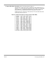
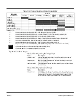
Eight different operating modes are available in the Series 18H vector control. These
operating modes define the basic motor control setup and the operation of the input and
output terminals. After the circuit connections are completed, the operating mode is
selected by programming the Operating Mode parameter in the Level 1 Input
programming Block. Available operating modes include:
•
Keypad Control
•
Standard Run, 3 Wire Control
•
15 Speed, 2 Wire Control
•
Fan Pump 2 Wire Control
•
Fan Pump 3 Wire Control
•
Bipolar Speed or Torque
•
Process Control
•
Serial
Note: The Serial operating mode requires one of the optional Serial Interface
expansion boards (RS232 or 422/485). Installation and operation information
for these serial expansion boards is provided in Serial Communications
expansion board manual MN1310. This manual is shipped with the serial
expansion boards.
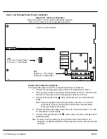
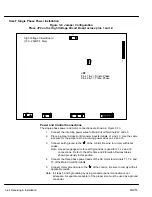
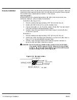
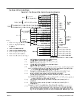
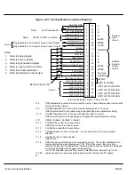
Keypad Mode Connections
To operate in the Keypad mode, set the Level 1 Input block, Operating Mode parameter
to Keypad. In this mode, only the External Trip Opto Input at J1-16 is active (if the Level
2 Protection block, External Trip parameter is set to ON). Both analog outputs remain
active. Connections are made as shown in Figure 3-20.
The STOP key can operate in either of two ways:
S
Press STOP key one time to brake or coast to stop (as set in the Level 1
Keypad Setup block, Keypad Stop Mode parameter).
S
Press STOP key two times to disable control.
Summary of Contents for 18H Series
Page 1: ...SERIES 18H AC Flux Vector Control Installation Operating Manual 9 97 MN718 VECTOR DRIVE ...
Page 105: ...Section 1 General Information 5 18 Troubleshooting MN718 ...
Page 109: ...Section 1 General Information 6 4 Manual Tuning the Series 18H Control MN718 ...
Page 144: ...Appendix C Appendix C 1 MN718 ...


