


Section 1
General Information
Programming & Operation 4-11
MN718
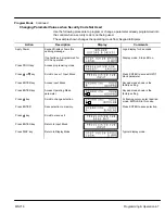
Table 4-2 Level 1 Parameter Block Definitions
Block Title
Parameter
Description
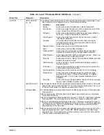
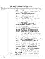
PRESET
SPEEDS
Preset Speeds
#1 – #15
Allows selection of 15 predefined motor operating speeds.
Each speed may be selected using external switches connected to J1-11, J1-12,
J1-13 and J1-14 when Operating Mode is set to 15 Speed.
For motor operation, a motor direction command must be given along with a preset
speed command.
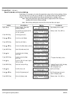
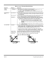
ACCEL/DECEL
RATE
Accel Time #1,2
Accel time is the number of seconds required for the motor to increase at a linear rate
from 0 RPM to the RPM specified in the “Max Output Speed” parameter in the Level 2
Output Limits block.
Decel Time #1,2
S-Curve #1 2
Out ut Limits block.
Decel time is the number of seconds required for the motor to decrease at a linear rate
from the speed specified in the “Max Output Speed” parameter to 0 RPM.
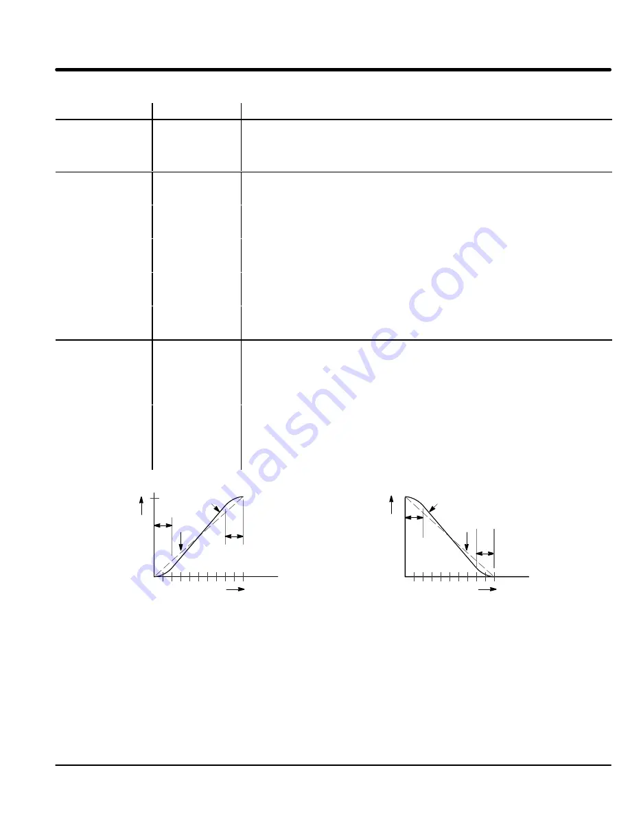
S-Curve is a percentage of the total Accel and Decel time and provides smooth starts
S-Curve #1,2
S-Curve is a percentage of the total Accel and Decel time and provides smooth starts
and stops. Half of programmed S-Curve % applies to Accel and half to Decel ramps.
0% represents no “S” and 100% represents full “S” with no linear segment.
Note: Accel #1 Decel #1 and S Curve #1 are associated together Likewise
Note: Accel #1, Decel #1 and S-Curve #1 are associated together. Likewise,
Accel #2, Decel #2 and S-Curve #2 are associated together. These
associations can be used to control any Preset Speed or External Speed
command
command.
Note: If drive faults occur during rapid Accel or Decel, selecting an S-curve may
eliminate the faults.
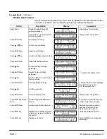
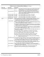
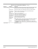
JOG SETTINGS
Jog Speed
Jog Speed is the programmed speed used during for jog. Jog can be initiated from the
keypad or terminal strip. At the Keypad, press the JOG key then press and hold the
direction (FWD or REV). For Standard Run mode, close the JOG input (J1-12) at the
direction (FWD or REV). For Standard Run mode, close the JOG in ut (J1 12) at the
terminal strip then close and maintain the direction input (J1-9 or J1-10).
Process Control mode operation is different. If the terminal strip Process Mode
E
bl i
(J1 13) i
l
d
i
h K
d JOG k
(
l
i
J1 14)
ill
Jog Accel Time
Enable input (J1-13) is closed, pressing the Keypad JOG key (or closing J1-14) will
cause the drive to move in the direction of the error (without pressing FWD or REV).
Jog Accel Time changes the Accel Time to a new preset value for jog mode.
Jog Accel Time
Jog Decel Time
Jog S-Curve
Jog Accel Time changes the Accel Time to a new reset value for jog mode.
Jog Decel Time changes the Decel Time to a new preset value for jog mode.
Jog S-Curve changes the S-Curve to a new preset value for jog mode.
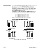
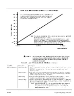
Figure 4-2 40% S-Curve Example
Output Speed
Accel Time
0
Accel S-Curves
20
%
20
%
0%
Curve
40%
Curve
Decel Time
0
Decel S-Curves
20
%
20
%
0%
Curve
40%
Curve
Output Speed
Summary of Contents for 18H Series
Page 1: ...SERIES 18H AC Flux Vector Control Installation Operating Manual 9 97 MN718 VECTOR DRIVE ...
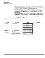
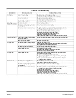
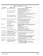
Page 105: ...Section 1 General Information 5 18 Troubleshooting MN718 ...
Page 109: ...Section 1 General Information 6 4 Manual Tuning the Series 18H Control MN718 ...
Page 144: ...Appendix C Appendix C 1 MN718 ...


