


Section 1
General Information
5-8 Troubleshooting
MN718
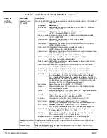
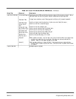
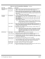
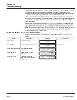
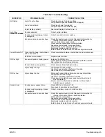
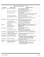
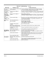
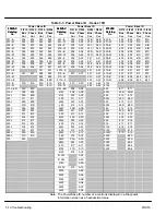
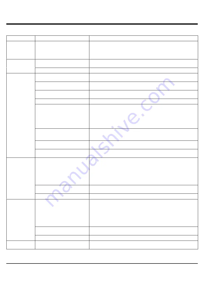
Table 5-2 Troubleshooting
Continued
INDICATION
POSSIBLE CAUSE
CORRECTIVE ACTION
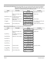
New Base ID
Software parameters are not
initialized on newly installed
control board.
Press “RESET” key on keypad to clear the fault condition. Cycle power
(turn power OFF then ON). Reset parameter values to factory settings.
Access diagnostics and compare power base ID number to list in Table 5-3
to ensure a match. Re-enter the Parameter Block Values you recorded in
the User Settings at the end of this manual. Autotune the control.
No EXB Installed
Incorrect operating mode
programmed.
Change Operating Mode in the Level 1 Input block to one that does not
require the expansion board.
Need expansion board.
Install the correct expansion board for selected operating mode.
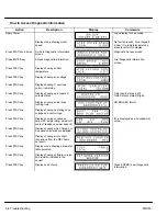
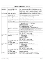
Over Current FLT
Current Limit parameter set lower
than drive rating.
Increase PK Current Limit parameter in the Level 2
Output Limits block, not to exceed drive rating.
ACCEL/DECEL time too short.
Increase ACCEL/DEC parameters in the Level 1
ACCEL/DECEL Rate block.
Encoder coupling slipping, broken
or misaligned.
Correct or replace encoder to motor coupling.
Encoder bearing failure.
Replace and align encoder.
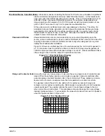
Excessive noise on encoder lines.
Check the position counter in the Diagnostic Information for
jittering which will confirm an encoder problem.
Check encoder connections.
Separate encoder leads from power wiring.
Cross encoder wires and power leads at 90
°
.
Electrically isolate encoder from motor.
Install optional Isolated Encoder Feedback expansion board.
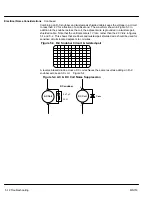
Electrical noise from external DC
coils.
Install reverse biased diodes across all external DC relay coils as shown in
the Opto Output circuit examples of this manual. See Electrical Noise
Considerations in Section 5 of this manual.
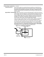
Electrical noise from external AC
coils.
Install RC snubbers on all external AC coils. See Electrical Noise
Considerations in Section 5 of this manual.
Excessive load.
Reduce the motor load.
Verify proper sizing of control and motor.
Overload - 3 Sec
FLT
Peak output current exceeded 3
second rating.
Check PK Current Limit parameter in the Level 2
Output Limits block.
Change Overload parameter In the Level 2 Protection block
from Trip to Foldback.
Check motor for overloading.
Increase ACCEL time.
Reduce motor load.
Verify proper sizing of control and motor.
Encoder coupling slipping, broken
or misaligned.
Correct or replace encoder to motor coupling.
Encoder bearing failure.
Replace and align encoder.
Overload - 1 Min
FLT
Peak output current exceeded 1
minute rating.
Check PK Current Limit parameter in the Level 2
Output Limits block.
Change Overload parameter In the Level 2 Protection block
from Trip to Foldback.
Check motor for overloading.
Increase ACCEL/DECEL times.
Reduce motor load.
Verify proper sizing of control and motor.
Encoder coupling slipping, broken
or misaligned.
Correct or replace encoder to motor coupling.
Encoder bearing failure.
Replace and align encoder.
Over Speed
Motor exceeded 110% of MAX
Speed parameter value.
Check Max Output Speed in the Level 2 Output Limits block.
Increase Speed PROP Gain in the Level 1 Vector Control block.
Summary of Contents for 18H Series
Page 1: ...SERIES 18H AC Flux Vector Control Installation Operating Manual 9 97 MN718 VECTOR DRIVE ...
Page 105: ...Section 1 General Information 5 18 Troubleshooting MN718 ...
Page 109: ...Section 1 General Information 6 4 Manual Tuning the Series 18H Control MN718 ...
Page 144: ...Appendix C Appendix C 1 MN718 ...


