


Section 1
General Information
3-4 Receiving & Installation
MN718
Electrical Installation
Interconnection wiring is required between the motor control, AC power source, motor,
host control and any operator interface stations. Use listed closed loop connectors that
are of appropriate size for wire gauge being used. Connectors are to be installed using
crimp tool specified by the manufacturer of the connector. Only Class 1 wiring should be
used.
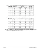
Baldor Series H controls feature UL approved adjustable motor overload protection
suitable for motors rated at no less than 50% of the output rating of the control. Other
governing agencies such as NEC may require separate over–current protection. The
installer of this equipment is responsible for complying with the National Electric Code
and any applicable local codes which govern such practices as wiring protection,
grounding, disconnects and other current protection.
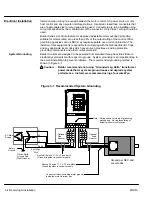
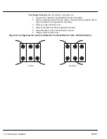
System Grounding
Baldor Controls are designed to be powered from standard three phase lines that are
electrically symmetrical with respect to ground. System grounding is an important step in
the overall installation to prevent problems. The recommended grounding method is
shown in Figure 3-1.
Caution:
Baldor recommends not using “Grounded Leg Delta” transformer
power leads that may create ground loops and degrade system
performance. Instead, we recommend using a four wire Wye.
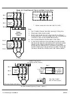
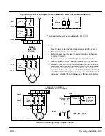
Figure 3-1 Recommended System Grounding
L1
AC Main
Supply
Safety
Ground
Driven Earth
Ground Rod
(Plant Ground)
Four Wire
“Wye”
L1
L2
L3
Earth
LOCAL
SHIFT
DISP
RESET
PROG
ENTER
JOG
STOP
REV
FWD
L2 L3
T1 T2 T3
Series H
Optional
Line
Reactor
Optional
Load
Reactor
Route all 4 wires L1, L2, L3 and Earth
(Ground) together in conduit or cable.
Route all 4 wires T1, T2, T3 and Motor
Ground together in conduit or cable.
Connect all wires (including motor ground)
inside the motor terminal box.
Ground per NEC and
Local codes.
Note: Wiring shown for clarity of grounding
method only. Not representative of
actual terminal block location.
Summary of Contents for 18H Series
Page 1: ...SERIES 18H AC Flux Vector Control Installation Operating Manual 9 97 MN718 VECTOR DRIVE ...
Page 105: ...Section 1 General Information 5 18 Troubleshooting MN718 ...
Page 109: ...Section 1 General Information 6 4 Manual Tuning the Series 18H Control MN718 ...
Page 144: ...Appendix C Appendix C 1 MN718 ...


