


Section 1
General Information
3-2 Receiving & Installation
MN718
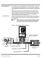
Control Installation
The control must be securely fastened to the mounting surface. Use the four (4)
mounting holes to fasten the control to the mounting surface or enclosure.
Shock Mounting
If the control will be subjected to levels of vibration greater than 0.5G at 10 to 60Hz, the
control should be shock mounted. Excessive vibration within the control could cause
internal connections to loosen and cause component failure or electrical shock hazard.
Through the Wall Mounting
Control sizes E and F are designed for panel or through the wall installation. To mount a
control through the wall, a Through the Wall mounting kit must be purchased. These kits
are:
Kit No.
Description
KT0000A00
Size A control through the wall mounting kit.
KT0001A00
Size B control through the wall mounting kit.
V0083991
Size E control through the wall mounting kit.
V0084001
Size F control through the wall mounting kit.
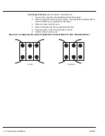
Procedure:
1.
Refer to Section 7 of this manual for drawings and dimensions of the through
the wall mounting kits. Use the information contained in these drawings to
layout the appropriate size hole on your enclosure and wall.
2.
Cut the holes in your enclosure and wall.
3.
Locate and drill holes for mounting hardware as shown in the drawings.
4.
Cut foam tape and apply to perimeter of opening as shown.
5.
Secure the four (4) brackets to the exterior of the customers panel with the
hardware provided.
6.
Secure the control to the customers panel using the hardware provided.
Summary of Contents for 18H Series
Page 1: ...SERIES 18H AC Flux Vector Control Installation Operating Manual 9 97 MN718 VECTOR DRIVE ...
Page 105: ...Section 1 General Information 5 18 Troubleshooting MN718 ...
Page 109: ...Section 1 General Information 6 4 Manual Tuning the Series 18H Control MN718 ...
Page 144: ...Appendix C Appendix C 1 MN718 ...


