


Section 1
General Information
3-8 Receiving & Installation
MN718
Analog Outputs
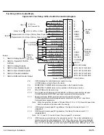
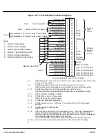
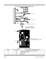
Two programmable analog outputs are provided on J1-6 and J1-7. See Figure 3-31.
These outputs are scaled 0 - 5 VDC (1mA maximum output current) and can be used to
provide real-time status of various control conditions. The output conditions are defined
in
Table NO TAG
of Section 4 of this manual.
The return for these outputs is J1-1 analog ground. Each output is programmed in the
Level 1 Output block.
1.
Connect the Output #1 wires to J1-6 and J1-1.
2.
Connect the Output #2 wires to J1-7 and J1-1.
Figure 3-31 Analog Outputs Equivalent Circuits
+
–
10K
W
10K
W
.033
m
f
50
W
6
From Microprocessor
+
–
10K
W
10K
W
.033
m
f
50
W
7
From Microprocessor
Notes:
+
–
All OP Amps are TL082 or TL084
Analog Ground is separated from
Chassis Ground. Electrically they
are separated by an RC network.
1
Terminal Tightening Torque = 7 Lb-in (0.8 Nm).
J1
Summary of Contents for 18H Series
Page 1: ...SERIES 18H AC Flux Vector Control Installation Operating Manual 9 97 MN718 VECTOR DRIVE ...
Page 105: ...Section 1 General Information 5 18 Troubleshooting MN718 ...
Page 109: ...Section 1 General Information 6 4 Manual Tuning the Series 18H Control MN718 ...
Page 144: ...Appendix C Appendix C 1 MN718 ...