


Section 1
General Information
3-30 Receiving & Installation
MN718
Encoder Installation
Electrical isolation of the encoder shaft and housing from the motor is required. Electrical
isolation prevents capacitive coupling of motor noise that will corrupt the encoder signals.
See electrical noise considerations in Section 7 of this manual.
Cable Preparation
Encoder wiring must be shielded twisted pairs, #22 AWG (0.34mm
2
) minimum size,
200
′
(60m) maximum, with an insulated overall shield.
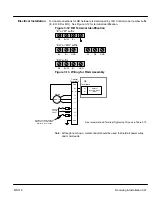
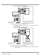
Control End (See Figure 3-16.)
1.
Strip the outside jacket approximately 0.375
″
(9.5mm) from the end.
2.
Solder a #22 AWG (0.34mm
2
) wire to the braided shield.
3.
Connect all shields to J1-30. To do this, solder a “Drain Wire” from each shield
to the wire soldered to the braided shield in step 2.
4.
Insulate or tape off ungrounded end of shields to prevent contact with other
conductors or ground.
Encoder End
1.
Strip the outside jacket approximately 0.375
″
(9.5mm) from the end.
2.
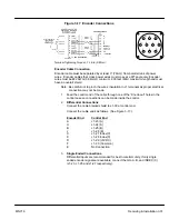
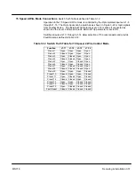
Identify each of the four twisted pair and label or use the color codes shown in
Figure 3-17 for the optional Baldor Encoder Cable.
3.
Insulate or tape off ungrounded end of shields and unused conductors to
prevent contact with other conductors or ground.
CAUTION: Do not connect any shields to the encoder case or motor frame.
The e5VDC supply at J1-29 is referenced to circuit board
common. Do not connect any shields to ground or another power
supply or damage to the control may result.
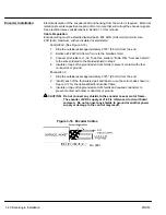
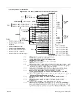
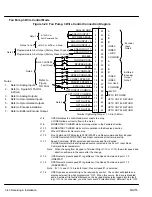
Figure 3-16 Encoder Cables
No. 9891
Summary of Contents for 18H Series
Page 1: ...SERIES 18H AC Flux Vector Control Installation Operating Manual 9 97 MN718 VECTOR DRIVE ...
Page 105: ...Section 1 General Information 5 18 Troubleshooting MN718 ...
Page 109: ...Section 1 General Information 6 4 Manual Tuning the Series 18H Control MN718 ...
Page 144: ...Appendix C Appendix C 1 MN718 ...


