


Section 1
General Information
3-28 Receiving & Installation
MN718
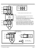
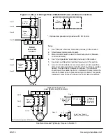
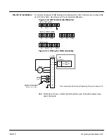
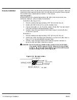
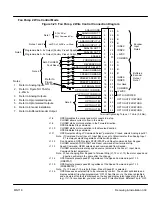
Figure 3-14 Wiring for RBA Assembly
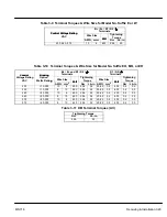
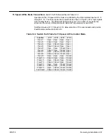
See recommended Terminal Tightening Torques in Section 7.
See recommended Terminal
Tightening Torques in Table 3-9.
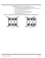
Optional Customer Supplied
Breaker or Fuse Protection -
Subject to Local Codes
MOTOR
50/60 Hz
3 Phase
Power
GND
B–
B+
T3
T2
T1
L3
L2
L1
GND
GND
T1
T2
T3
Optional
Dynamic Brake
(RBA)
D1
D2
D1
D2
B–
B+
Shielded
Twisted Pair
Control
Terminals
DB
Terminals
Note: Although not shown, metal conduit should be used to shield all power wires
and motor leads.
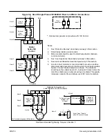
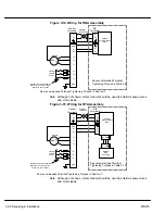
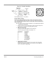
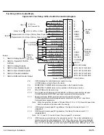
Figure 3-15 Wiring for RTA Assembly
See recommended Terminal Tightening Torques in Section 7.
See recommended Terminal
Tightening Torques in Table 3-10.
Optional Customer Supplied
Breaker or Fuse Protection -
Subject to Local Codes
MOTOR
50/60 Hz
3 Phase
Power
GND
B–
B+
T3
T2
T1
L3
L2
L1
GND
GND
T1
T2
T3
Optional
Dynamic Brake
(RTA)
D1
D2
D1
D2
B–
B+
R2
R1
R2
R1
Optional
RGA
Assembly
Shielded
Twisted Pair
Control
Terminals
DB
Terminals
Note: Although not shown, metal conduit should be used to shield all power wires
and motor leads.
Summary of Contents for 18H Series
Page 1: ...SERIES 18H AC Flux Vector Control Installation Operating Manual 9 97 MN718 VECTOR DRIVE ...
Page 105: ...Section 1 General Information 5 18 Troubleshooting MN718 ...
Page 109: ...Section 1 General Information 6 4 Manual Tuning the Series 18H Control MN718 ...
Page 144: ...Appendix C Appendix C 1 MN718 ...


