


Section 1
General Information
3-12 Receiving & Installation
MN718
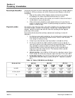
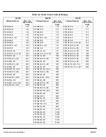
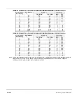
Table 3-6 Wire Size and Protection Devices - 575 VAC Controls
Control O tp t
Inp t
Inp t F se
Wire Ga ge
Control Output
P
R ti
Input
B
k
Input Fuse
Wire Gauge
p
Power Rating
p
Breaker
Fast Acting
Time Delay
AWG
mm
2
1
5A
5A
4A
14
2.5
2
10A
5A
4A
14
2.5
3
10A
6A
5A
14
2.5
5
10A
10A
7A
14
2.5
7.5
10A
15A
10A
14
2.5
10
15A
15A
12A
14
2.5
15
20A
25A
20A
12
4
20
25A
35A
25A
10
6
25
30A
40A
30A
8
10
30
35A
50A
35A
8
10
40
45A
60A
45A
6
16
50
60A
80A
60A
4
25
60
70A
90A
70A
4
25
75
120A
150A
120A
3
27
100
120A
150A
120A
1/0
54
125
150A
200A
150A
2/0
70
150
175A
225A
175A
2/0
70
Note: All wire sizes based on 75
°
C copper wire, 3% line impedance. Higher temperature smaller gauge wire may be
used per NEC and local codes. Recommended fuses/breakers are based on 25
°
C ambient, maximum
continuous control output current and no harmonic current.
Summary of Contents for 18H Series
Page 1: ...SERIES 18H AC Flux Vector Control Installation Operating Manual 9 97 MN718 VECTOR DRIVE ...
Page 105: ...Section 1 General Information 5 18 Troubleshooting MN718 ...
Page 109: ...Section 1 General Information 6 4 Manual Tuning the Series 18H Control MN718 ...
Page 144: ...Appendix C Appendix C 1 MN718 ...


