


Section 1
General Information
4-10 Programming & Operation
MN718
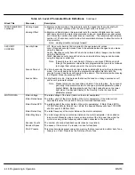
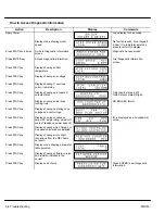
Parameter Definitions
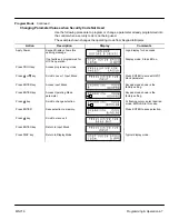
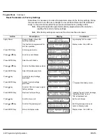
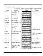
To make programming easier, parameters have been arranged as shown in Table 4-1. Press
the PROG key to enter the programming mode and the “Preset Speeds” programming block
will be displayed. Use the Up (
Y
) and Down (
B
) arrows to scroll through the parameter
blocks. Press ENTER to access parameters within a programing block.
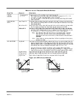
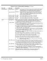
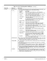
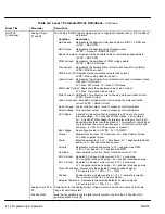
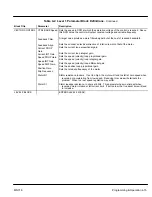
Tables 4-2 and 4-3 provide an explanation of each parameter. A complete Parameter Block
Values list is located at the end of this manual. This list defines the programmable range and
preset value for each parameter and has space to record your settings for future reference.
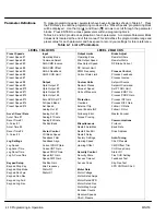
Table 4-1 List of Parameters
LEVEL 1 BLOCKS
LEVEL 2 BLOCKS
Preset Speeds
Input
Output Limits
Brake Adjust
Preset Speed #1
Operating Mode
Operating Zone
Resistor Ohms
Preset Speed #2
Command Select
Min Output Speed
Resistor Watts
Preset Speed #3
ANA CMD Inverse
Max Output Speed
DC Brake Current
Preset Speed #4
ANA CMD Offset
PK Current Limit
Preset Speed #5
ANA 2 Deadband
PWM Frequency
Process Control
Preset Speed #6
ANA1 CUR Limit
Current Rate Limit
Process Feedback
Preset Speed #7
Process Inverse
Preset Speed #8
Output
Custom Units
Setpoint Source
Preset Speed #9
Opto Output #1
Decimal Places
Setpoint Command
Preset Speed #10
Opto Output #2
Value at Speed
Set PT ADJ Limit
Preset Speed #11
Opto Output #3
Units of Measure
Process ERR TOL
Preset Speed #12
Opto Output #4
Process PROP Gain
Preset Speed #13
Zero SPD Set PT
Protection
Process INT Gain
Preset Speed #14
At Speed Band
Overload
Process DIFF Gain
Preset Speed #15
Set Speed
External Trip
Follow I:O Ratio
Analog Out #1
Local Enable INP
Follow I:O Out
Accel / Decel Rate
Analog Out #2
Following Error
Master Encoder
Accel Time #1
Analog #1 Scale
Torque Proving
Decel Time #1
Analog #2 Scale
Communications
S-Curve #1
Position Band
Miscellaneous
Protocol
Accel Time #2
Restart Auto/Man
Baud Rate
Decel Time #2
Vector Control
Restart Fault/Hr
Drive Address
S-Curve #2
Ctrl Base Speed
Restart Delay
Feedback Filter
Factory Settings
Auto-Tuning
Jog Settings
Feedback Align
Homing Speed
CALC Presets
Jog Speed
Current PROP Gain
Homing Offset
CMD Offset Trim
Jog Accel Time
Current INT Gain
CUR Loop Comp
Jog Decel Time
Speed PROP Gain
Security Control
Stator R1
Jog S-Curve Time
Speed INT Gain
Security State
Flux CUR Setting
Speed DIFF Gain
Access Timeout
Feedback Test
Keypad Setup
Position Gain
Access Code
Slip Freq Test
Keypad Stop Key
Slip Frequency
SPD CNTRLR CALC
Keypad Stop Mode
Stator R1
Motor Data
Keypad Run Fwd
Stator X1
Motor Voltage
Keypad Run Rev
Motor Rated Amps
Keypad Jog Fwd
Motor Rated SPD
Keypad Jog Rev
Motor Rated Freq
Motor Mag Amps
Encoder Counts
Resolver Speeds
CALC Presets
Summary of Contents for 18H Series
Page 1: ...SERIES 18H AC Flux Vector Control Installation Operating Manual 9 97 MN718 VECTOR DRIVE ...
Page 105: ...Section 1 General Information 5 18 Troubleshooting MN718 ...
Page 109: ...Section 1 General Information 6 4 Manual Tuning the Series 18H Control MN718 ...
Page 144: ...Appendix C Appendix C 1 MN718 ...


