EyeQ uses a phase interpolator and sampler to estimate the vertical and horizontal eye opening using the
values that you specify for the horizontal phase and vertical height as described in the
Table 16-12
table.
The phase interpolator generates a sampling clock and the sampler examines the data from the sampler
output. As the phase interpolator output clock phase is shifted by small increments, the data error rate
goes from high to low to high if the receiver is good. The number of steps of valid data is defined as the
width of the eye. If none of the steps yields valid data, the width of the eye is equal to 0, which means the
eye is closed.
When the Bit Error Rate Block (BERB) is not enabled, the sampled data is deserialized and sent to the IP
core; the PRBS checker determines the Bit Error Rate (BER). When the BER Block is enabled, the Bit
checker determines the BER by comparing the sampled data to the CDR sampled data.
Note: If you are using the EyeQ monitor with DFE enabled, you must put the EyeQ monitor in 1D mode
by writing the EyeQ 1D-eye bit. For more information, refer to the
Table 16-12
table . The EyeQ
path is designed to measure the sampled eye margin. To estimate the pre-CDR eye opening using
the measured eye margin data, you can add 10ps to the measured eye margin value for RX input
signals with moderate amounts of jitter which is typical in most data streams.
The following table lists the memory-mapped EyeQ registers that you can access using Avalon-MM reads
and writes on reconfiguration management interface.
Note: All channels connected to same Transceiver Reconfiguration Controller IP Core share one set of
bit error rate block counters. You can monitor one channel at a time. If Transceiver Reconfigura‐
tion Controller is interrupted by other operations, such as channel switching or AEQ, the bit error
rate data will be corrupted.
Note: All undefined register bits are reserved.
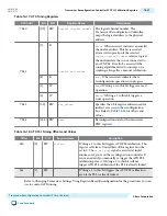
Table 16-11: Eye Monitor Registers
Note: The default value for all the register bits mentioned in this table is 0.
Reconfig Addr
Bits
R/W
Register Name
Description
7’h10
[9:0] RW
logical channel number
The logical channel number. Must be
specified when performing dynamic
updates. The Transceiver Reconfiguration
Controller maps the logical address to the
physical address.
7’h12
[9]
R
control and status
Error
.When asserted, indicates an invalid
channel or address.
[8]
R
Busy
. When asserted, indicates that a
reconfiguration operation is in progress.
[1]
W
Read
. Writing a 1 to this bit triggers a read
operation.
[0]
W
Write
. Writing a 1 to this bit triggers a
write operation.
7’h13
[5:0] RW
eyeq offset
Specifies the 6-bit offset of the EyeQ
register.
7’h14
[15:0] RW
data
Reconfiguration data for the transceiver
PHY registers.
UG-01080
2015.01.19
Transceiver Reconfiguration Controller EyeQ Registers
16-17
Transceiver Reconfiguration Controller IP Core Overview
Altera Corporation
Send Feedback

