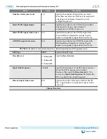


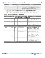

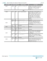


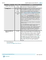
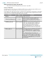


Table 11-19: Reconfiguration Interface
This table lists the signals in the reconfiguration interface. This interface uses the Avalon-MM PHY Management
interface clock.
Signal Name
Direction
Description
reconfig_to_xcvr [(<n>70)-1:0]
Input
Reconfiguration signals from the Transceiver
Reconfiguration Controller.
<n>
grows
linearly with the number of reconfiguration
interfaces.
reconfig_from_xcvr [(<n>46)-1:0]
Output
Reconfiguration signals to the Transceiver
Reconfiguration Controller.
<n>
grows
linearly with the number of reconfiguration
interfaces.
Related Information
Transceiver Reconfiguration Controller to PHY IP Connectivity
on page 16-56
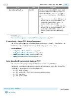
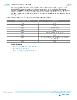
Channel Placement and Utilization for Deterministic Latency PHY
This section describes the channel placement utilization restrictions for the Deterministic Latency PHY IP
core.
The Deterministic Latency PHY IP Core has the following restriction on channel placement:
• Channels 1 and 2 in transceiver banks GXB_L0 and GXB_R0 of Arria V devices are not available for
deterministic latency protocols. However, in Arria V GZ devices, these channels are available for
deterministic latency protocols.
The following figure shows the placement of transceiver banks in Arria V devices and indicates the
channels that are not available.
11-28
Channel Placement and Utilization for Deterministic Latency PHY
UG-01080
2015.01.19
Altera Corporation
Deterministic Latency PHY IP Core
Send Feedback