


The Quartus II software reports timing violations for asynchronous inputs to the Standard PCS. Because
many violations are for asynchronous paths, they do not represent actual timing failures. You may choose
one of the following three approaches to identify these false timing paths to the Quartus II or TimeQuest
software.
• You can cut these paths in your Synopsys Design Constraints (.sdc) file by using the
set_false_path
command as shown in the following example.
Example 15-1: Using the set_false_path Constraint to Identify Asynchronous Inputs
set_false_path -through {*8gbitslip*} -to [get_registers
*8g_rx_pcs*SYNC_DATA_REG*]
set_false_path -through {*8gbytordpld*} -to [get_registers
*8g_rx_pcs*SYNC_DATA_REG*]
set_false_path -through {*8gcmpfifoburst*} -to [get_registers
*8g_rx_pcs*SYNC_DATA_REG*]
set_false_path -through {*8gphfifoburstrx*} -to [get_registers
*8g_rx_pcs*SYNC_DATA_REG*]
set_false_path -through {*8gsyncsmen*} -to [get_registers
*8g*pcs*SYNC_DATA_REG*]
set_false_path -through {*8gwrdisablerx*} -to [get_registers
*8g_rx_pcs*SYNC_DATA_REG*]
set_false_path -through {*rxpolarity*} -to [get_registers *SYNC_DATA_REG*]
set_false_path -through {*pldeidleinfersel*} -to [get_registers
*SYNC_DATA_REG*]
• You can use the
set_max_delay
constraint on a given path to create a constraint for asynchronous
signals that do not have a specific clock relationship but require a maximum path delay.
Example 15-2: Using the max_delay Constraint to Identify Asynchronous Inputs
# Example: Apply 10ns max delay
set_max_delay -from *tx_from_fifo* -to *8g*pcs*SYNC_DATA_REG1 10
• You can use the
set_false
path command only during Timequest timing analysis.
Example 15-3: Using the set_false TimeQuest Constraint to Identify Asynchronous Inputs
#if {$::TimeQuestInfo(nameofexecutable) eq "quartus_fit"} {
#} else {
#set_false_path -from [get_registers {*tx_from_fifo*}] -through
{*txbursten*} -to [get_registers *8g_*_pcs*SYNC_DATA_REG
Note: In all of these examples, you must substitute your actual signal names for the signal names shown.
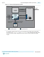
Dynamic Reconfiguration
Dynamic reconfiguration calibrates each channel to compensate for variations due to process, voltage,
and temperature (PVT).
These process variations result in analog voltages that can be offset from required ranges. The calibration
performed by the dynamic reconfiguration interface compensates for variations due to PVT.
UG-01080
2015.01.19
Dynamic Reconfiguration
15-33
Cyclone V Transceiver Native PHY IP Core Overview
Altera Corporation
Send Feedback