


Transceiver Reconfiguration Controller PLL Reconfiguration
You can use the PLL reconfiguration registers to change the reference clock input to the TX PLL or the
clock data recovery (CDR) circuitry.
The PLL registers for dynamic reconfiguration feature are available when you select one of the following
transceiver PHY IP cores:
• Custom PHY IP Core
• Low Latency PHY IP Core
• Deterministic Latency PHY IP Core
• Arria V, Arria V GZ, Cyclone V, and Stratix V Native PHYs
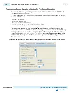
You can establish the number of possible PLL configurations on the Reconfiguration tab of the
appropriate transceiver PHY IP core. The Reconfiguration tab allows you to specify up to five input
reference clocks and up to four TX PLLs. You can also change the input clock source to the CDR PLL; up
to five input clock sources are possible. If you plan to dynamically reconfigure the PLLs in your design,
you must also enable
Allow PLL Reconfiguration
and specify the Main TX PLL logical index
which is the PLL that the Quartus II software instantiates at power up. The following figures illustrates
these parameters.
Figure 16-4: Reconfiguration Tab of Custom, Low Latency, and Deterministic Latency Transceiver PHYs
16-28
Transceiver Reconfiguration Controller PLL Reconfiguration
UG-01080
2015.01.19
Altera Corporation
Transceiver Reconfiguration Controller IP Core Overview
Send Feedback