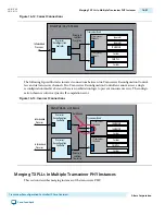
Figure 17-1: Typical System Diagram for the Transceiver PHY Reset Controller IP Core
This figure illustrates the typical use of Transceiver PHY Reset Controller in a design that includes a
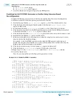
transceiver PHY instance and the Transceiver Reconfiguration Controller IP Core. You can use the
phy_mgmt_clk and phy_mgmt_clk_reset as the clock and reset to the user-controller reset logic.
clock (1)
reset (1)
tx_cal_busy
rx_cal_busy
Transceiver PHY Instance
Transceiver PHY
Reset Controller
rx_is_lockedtoref
pll_locked
rx_is_lockedtodata
reconfig_busy
mgmt_rst_reset
mgmt_clk_clk
reconfig_from_xcvr
reconfig_to_xcvr
Transceiver
Reconfiguration
Controller
rx_digitalreset
pll_powerdown
rx_analogreset
tx_ready
rx_ready
tx_digitalreset
Receiver
PMA
CDR
Transmitter
PCS
Transmitter
PMA
Receiver
PCS
tx_analogreset
Transmitter
PLL
(19)
As figure illustrates, the Transceiver PHY Reset Controller connects to a Transceiver PHY. The
Transceiver PHY Reset Controller IP Core drives TX and RX resets to the Transceiver PHY and receives
status from the Transceiver PHY. Depending on the components in the design, the calibration busy signal
may be an output of the Transceiver PHY or the Transceiver Reconfiguration Controller. The following
transceiver PHY IP support the removal of the embedded reset controller:
• Custom Transceiver PHY IP Core
• Low Latency PHY IP Core
• Deterministic Latency PHY IP Core
• Arria V and Stratix V Native PHY IP Cores
These transceiver PHYs drive the TX and RX calibration busy signals to the Transceiver PHY Reset
Controller IP Core.
(19)
You can use the phy_mgmt_clk and phy_mgmt_clk_reset as the clock and reset to the user-controller reset
logic.
17-2
Transceiver PHY Reset Controller IP Core
UG-01080
2015.01.19
Altera Corporation
Transceiver PHY Reset Controller IP Core
Send Feedback


