RX Data Word
Description
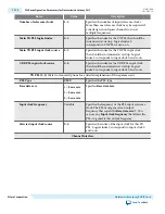
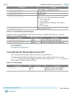
rx_parallel_data[10]
Word Aligner / synchronization status
rx_parallel_data[11]
Disparity error
rx_parallel_data[12]
Pattern detect
rx_parallel_data[14:13]
FIFO status. The following encodings are defined:
• 2’b00: Normal data
• 2’b01: Deletion
• 2’b10: Insertion (or Underflow with 9’h1FE or
9’h1F7)
• 2’b11: Overflow
rx_parallel_data[15]
Running disparity value
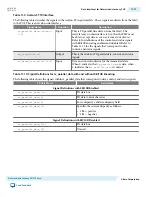
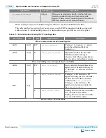
Table 11-13: Serial Interface and Status Signals
This table describes the differential serial data interface and the status signals for the transceiver serial data
interface. <
n
> is the number of lanes.
Signal Name
Direction
Signal Name
rx_serial_data[<n>-:0]
Input
Receiver differential serial input data.
tx_serial_data[<n>-:0]
Output
Transmitter differential serial output data.
Related Information
Avalon Interface Specifications
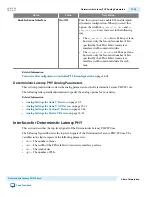
Clock Interface for Deterministic Latency PHY
This section describes the clocks for the Deterministic Latency PHY IP core.
The following table describes clocks for the Deterministic Latency PHY. The input reference clock,
pll_ref_clk
, drives a PLL inside the PHY-layer block, and a PLL output clock,
rx_clkout
is used for all
data, command, and status inputs and outputs.
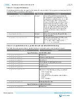
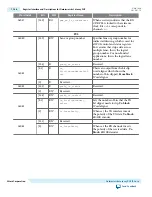
Table 11-14: Clock Signals
Signal Name
Direction
Description
pll_ref_clk
Input
Reference clock for the PHY PLLs.
Frequency range is 60-700 MHz.
UG-01080
2015.01.19
Clock Interface for Deterministic Latency PHY
11-19
Deterministic Latency PHY IP Core
Altera Corporation
Send Feedback


