PCS
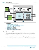
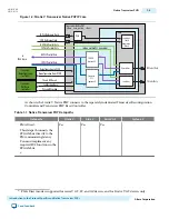
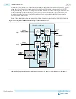
The PCS implements part of the physical layer specification for networking protocols. Depending upon
the protocol that you choose, the PCS may include many different functions. Some of the most commonly
included functions are: 8B/10B, 64B/66B, or 64B/67B encoding and decoding, rate matching and clock
compensation, scrambling and descrambling, word alignment, phase compensation, error monitoring,
and gearbox.
PMA
The PMA receives and transmits differential serial data on the device external pins. The transmit (TX)
channel supports programmable pre-emphasis and programmable output differential voltage (VOD). It
converts parallel input data streams to serial data. The receive (RX) channel supports offset cancellation to
correct for process variation and programmable equalization. It converts serial data to parallel data for
processing in the PCS. The PMA also includes a clock data recovery (CDR) module with separate CDR
logic for each RX channel.
Avalon-MM PHY Management Interface
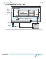
You can use the Avalon-MM PHY Management module to read and write the control and status registers
in the PCS and PMA for the protocol-specific transceiver PHY. The Avalon-MM PHY Management
module includes both Avalon-MM master and slave ports and acts as a bridge. It transfers commands
received from an embedded controller on its slave port to its master port. The Avalon-MM PHY
management master interface connects the Avalon-MM slave ports of PCS and PMA registers and the
Transceiver Reconfiguration module, allowing you to manage these Avalon-MM slave components
through a simple, standard interface. (Refer to Transceiver PHY Top-Level Modules.)
Transceiver Reconfiguration Controller
Altera Transceiver Reconfiguration Controller dynamically reconfigures analog settings in Arria V,
Cyclone V, and Stratix V devices.
Reconfiguration allows you to compensate for variations due to process, voltage, and temperature (PVT)
in 28-nm devices. It is required for Arria V, Cyclone V, and Stratix V devices that include transceivers.
For more information about the Transceiver Reconfiguration Controller, refer to Transceiver Reconfigu‐
ration Controller IP Core. The reset controller may be included in the transceiver PHY or may be a
separately instantiated component as described in Transceiver PHY Reset Controller.
Related Information
Transceiver Reconfiguration Controller IP Core Overview
on page 16-1
Resetting the Transceiver PHY
This section provides an overview of the embedded reset controller and the separately instantiated
Transceiver PHY Reset Controller IP Core.
The embedded reset controller ensures reliable transceiver link initialization. The reset controller initial‐
izes both the TX and RX channels. You can disable the automatic reset controller in the Custom, Low
Latency Transceiver, and Deterministic Latency PHYs. If you disable the embedded reset controller, the
powerdown, analog and digital reset signals for both the TX and RX channels are top-level ports of the
transceiver PHY. You can use these ports to design a custom reset sequence, or you can use the Altera-
provided Transceiver Reset Controller IP Core.
UG-01080
2015.01.19
Transceiver Reconfiguration Controller
1-5
Introduction to the Protocol-Specific and Native Transceiver PHYs
Altera Corporation
Send Feedback

