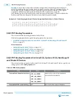
Example 5-1: Edits to a MIF to Remove PMA Settings
Creating a 1G/10GbE Design
Here are the steps you must take to create a 1G/10GbE design using this PHY.
1. Generate the 1G/10GbE PHY with the required parameterization.
2. Generate a Transceiver Reconfiguration Controller with the correct number of reconfiguration
interfaces based on the number of channels you are using. This controller is connected to all the
transceiver channels. It implements the reconfiguration process.
3. Generate a Transceiver Reset Controller.
4. Create arbitration logic that prioritizes simultaneous reconfiguration requests from multiple channels.
This logic should also acknowledge the channel being serviced causing the requestor to deassert its
request signal.
5. Create a state machine that controls the reconfiguration process. The state machine should:
a. Receive the prioritized reconfiguration request from the arbiter
b. Put the Transceiver Reconfiguration Controller into MIF streaming mode.
c. Select the correct MIF and stream it into the appropriate channel.
d. Wait for the reconfiguration process to end and provide status signal to arbiter.
6. Generate one ROM for each required configuration.
7. Create a MIF for each configuration and associate each MIF with a ROM created in Step 6. For
example, create a MIF for 1G with 1588 and a MIF for 10G with 1588. These MIFs are the two configu‐
rations used in the MIF streaming process.
5-24
Creating a 1G/10GbE Design
UG-01080
2015.01.19
Altera Corporation
1G/10 Gbps Ethernet PHY IP Core
Send Feedback


