


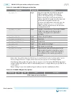


Signal Name
Direction
Description
reconfig_from_xcvr [(<n>/4)
17-1:0]
Output
Reconfiguration RAM. The PHY device drives this
RAM data to the transceiver reconfiguration IP. This
signal is only available in Stratix IV devices.
10GBASE-R PHY Dynamic Reconfiguration for Arria V and Stratix V
Devices
For Arria V and Stratix V devices, each channel and each TX PLL have separate dynamic reconfiguration
interfaces. The MegaWizard Plug-In Manager provides informational messages on the connectivity of
these interfaces. The example below shows the messages for a single duplex channel.
Although you must initially create a separate reconfiguration interface for each channel and TX PLL in
your design, when the Quartus II software compiles your design, it reduces the number of reconfiguration
interfaces by merging reconfiguration interfaces. The synthesized design typically includes a reconfigura‐
tion interface for at least three channels because three channels share an Avalon-MM slave interface
which connects to the Transceiver Reconfiguration Controller IP Core. Conversely, you cannot connect
the three channels that share an Avalon-MM interface to different Transceiver Reconfiguration Control‐
lers. Doing so causes a Fitter error. For more information, refer to
Transceiver Reconfiguration
Controller to PHY IP Connectivity
on page 16-56. Allowing the Quartus II software to merge reconfi‐
guration interfaces gives the Fitter more flexibility in placing transceiver channels.
Example 3-2: Informational Messages for the Transceiver Reconfiguration Interface
Reconfiguration interface offset 0 is connected to the transceiver channel.
PHY IP will require 2 reconfiguration interfaces for connection to the external
reconfiguration controller.
Reconfiguration interface offset 0 is connected to the transceiver channel.
Reconfiguration interface offset 1 is connected to the transmit PLL.
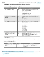
The following table describes the signals in the reconfiguration interface; this interface uses the Avalon-
MM PHY Management interface clock.
Table 3-18: Reconfiguration Interface
Signal Name
Directio
n
Description
reconfig_to_xcvr
[(<n>70-1):0]
Input
Reconfiguration signals from the Transceiver Reconfigura‐
tion Controller. <
n
> grows linearly with the number of
reconfiguration interfaces. This signal is only available in
Stratix V devices.
reconfig_from_xcvr
[(<n>46-1):0]
Output Reconfiguration signals to the Transceiver Reconfiguration
Controller. <
n
> grows linearly with the number of reconfi‐
guration interfaces. This signal is only available in Stratix V
devices.
UG-01080
2015.01.19
10GBASE-R PHY Dynamic Reconfiguration for Arria V and Stratix V Devices
3-29
10GBASE-R PHY IP Core
Altera Corporation
Send Feedback