


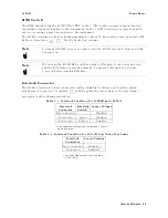


4339B
Front
P
anel
V
Output
Indicator
The
V
output
indicator
indicates
that
the
test
voltage
is
applied
to
the
DUT
.
Source
V
oltage
key
The
source
voltage
key
sets
the
test
voltage
value
from
0
to
1000
V
.
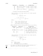
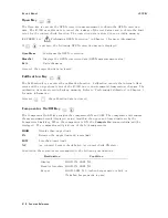
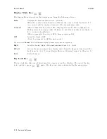
Resolution
of
the
test
voltage
is
as
follows:
V
oltage
Range
Resolution
0
V
T
est
V
oltage
200
V
0.1
V
200
V
<
T
est
V
oltage
1000
V
1
V
Current
Limit
K
ey
The
current
limit
key
sets
the
limitation
value
of
current
owing
through
the
DUT
.
The
4339B
adjusts
the
test
voltage
so
that
the
current
owing
through
the
DUT
does
not
exceed
the
current
limit
value
.
While
the
current
limit
is
active
and
the
source
output
is
decreased,
the
4339B
displays
\OVER
CURRENT ".
The
current
limitation
feature
protects
the
DUT
from
destruction
due
to
high
current
ow
.
Current
limits
can
be
set
to
the
following
values:
0.5
mA
(default)
1
mA
2
mA
(at
test
voltage
0
to
500
V
only)
5
mA
(at
test
voltage
0
to
250
V
only)
10
mA
(at
test
voltage
0
to
100
V
only)
Note
When
the
16117B
Low
Noise
T
est
Leads
are
used,
the
available
current
limit
setting
is
0.5
mA
only
.
Measurement
Time
key
The
measurement
time
key
sets
measurement
time
mode:
Short,
Medium(Med ),
or
Long.
A
longer
measurement
time
produces
a
more
accurate
measurement
result.
The
current
measurement
time
mode
setting
is
indicated
by
the
Meas
Time
annunciator(
9
).
The
default
setting
is
Medium.
A
verage
key
The
average
key
sets
the
measurement
averaging
rate
.
The
4339B
automatically
averages
the
measurement
results
by
this
rate
.
The
averaging
rate
can
be
set
as
an
integer
from
1
to
256.
The
default
setting
is
1.
Function
Reference
3-5
Summary of Contents for 4339B
Page 10: ......
Page 18: ... ᄌᦝ 0123 45 6789 8 A B C ᄌᦝ 3 DE FG H FG IJ B C K 9 C Copyright 2007 Agilent Technologies ...
Page 20: ......
Page 21: ......
Page 22: ......
Page 24: ......
Page 25: ......
Page 26: ......
Page 30: ......
Page 44: ......
Page 55: ...4339B Initial Inspection Figure 1 1 Power Cable Supplied Getting Started 1 11 ...
Page 212: ......
Page 220: ......
Page 230: ......
Page 256: ......
Page 268: ...Procedure 4339B Figure B 5 A1 Main Board B 8 Handler Interface Installation ...


