


4339B
Theory
of
Operation
Overall
Block
Diagram
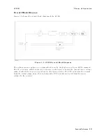
Figure
3-9
shows
the
overall
block
diagram
of
the
4339B.
Figure
3-9.
4339B
Overall
Block
Diagram
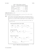
The
voltage
source
applies
a
dc
voltage
which
is
set
by
the
keyboard
or
by
an
GPIB
command.
The
I-V
converter
,
which
is
directly
connected
to
the
input,
converts
the
current
into
a
voltage
ramp
,
of
which
the
slope
is
proportional
to
the
input
current.
The
CPU
calculates
the
current
from
the
voltage
ramp
slope
,
then
calculates
the
DUT's
resistance
by
dividing
the
source
voltage
by
the
current.
Function
Reference
3-27
Summary of Contents for 4339B
Page 10: ......
Page 18: ... ᄌᦝ 0123 45 6789 8 A B C ᄌᦝ 3 DE FG H FG IJ B C K 9 C Copyright 2007 Agilent Technologies ...
Page 20: ......
Page 21: ......
Page 22: ......
Page 24: ......
Page 25: ......
Page 26: ......
Page 30: ......
Page 44: ......
Page 55: ...4339B Initial Inspection Figure 1 1 Power Cable Supplied Getting Started 1 11 ...
Page 212: ......
Page 220: ......
Page 230: ......
Page 256: ......
Page 268: ...Procedure 4339B Figure B 5 A1 Main Board B 8 Handler Interface Installation ...


