


P
erformance
T
ests
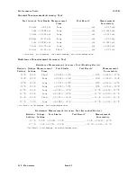
4339B
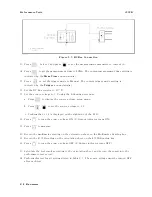
Figure
9-7.
RC
Box
Connection
(Floating)
12.
Press
to
set
the
measurement
time
to
SHORT
.
The
current
measurement
time
setting
is
indicated
by
the
Meas
Time
annunciator(
9
).
13.
Press
to
set
the
trigger
mode
to
Manual.
The
current
trigger
mode
setting
is
indicated
by
the
Trigger
annunciator(
9
).
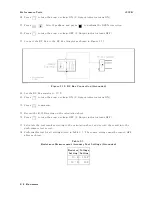
14.
Set
the
RC
Box
resistor
to
10
6
.
15.
Press
to
turn
the
source
voltage
ON.
(V
Output
indicator
lights
.)
16.
Press
to
measure
.
17.
Record
the
4339B
reading
on
the
calculation
sheet.
18.
Press
to
turn
the
source
voltage
OFF
.
(V
Output
indicator
turns
OFF
.)
19.
Calculate
the
test
result
according
to
the
calculation
sheet,
and
record
the
result
into
the
performance
test
record.
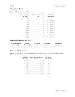
20.
P
erform
the
test
for
all
settings
listed
in
T
able
9-4 .
The
source
voltage
must
be
turned
OFF
after
each
test.
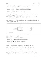
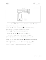
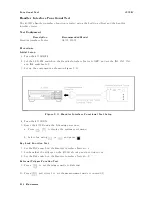
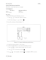
In
the
test
for
the
10
11
resistor
,
connect
the
RC
Box
A
dapter
to
the
10
11
terminals
and
set
the
10
11
switch
to
the
BNC
connector
position
as
shown
in
Figure
9-8.
Figure
9-8.
RC
Box
Connection
for
10
11
Resistor
9-14
Maintenance
Summary of Contents for 4339B
Page 10: ......
Page 18: ... ᄌᦝ 0123 45 6789 8 A B C ᄌᦝ 3 DE FG H FG IJ B C K 9 C Copyright 2007 Agilent Technologies ...
Page 20: ......
Page 21: ......
Page 22: ......
Page 24: ......
Page 25: ......
Page 26: ......
Page 30: ......
Page 44: ......
Page 55: ...4339B Initial Inspection Figure 1 1 Power Cable Supplied Getting Started 1 11 ...
Page 212: ......
Page 220: ......
Page 230: ......
Page 256: ......
Page 268: ...Procedure 4339B Figure B 5 A1 Main Board B 8 Handler Interface Installation ...


