


4339B
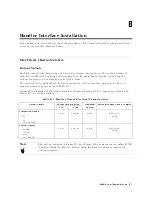
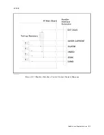
Procedure
Setting
Up
the
Handler
Interface
Board
Caution
SUSCEPTIBLE
TO
D
AMA
GE
FROM
ESD
.
P
erform
the
following
procedures
only
at
a
static-safe
workstation
and
wear
a
grounding
strap
.
Caution
Be
careful
not
to
short
the
circuit
when
performing
the
following
procedures
.
F
or
example:
Solder
cleanly
and
carefully
.
Guard
against
hair
or
dust
getting
on
the
circuit.
Do
not
damage
the
boards
,
wires
,
or
parts
on
the
board.
T
ools
and
F
asteners
The
4339B
mechanical
components
are
secured
using
metric
threaded
fasteners
.
Many
fasteners
in
the
4339B
may
appear
to
be
Phillips
type
,
but
they
are
P
ozidrive
type
fasteners
.
T
o
avoid
damaging
them,
use
only
P
ozidrive
screwdrivers
to
remove
or
tighten
pozidrive
type
fasteners
.
Procedure
1.
Disconnect
the
power
cable
from
the
4339B
and
allow
enough
time
(10
minutes)
for
the
internal
capacitors
to
discharge
.
W
arning
Dangerous
energy
and
voltage
levels
exist
within
the
4339B
when
it
is
in
operation
and
just
after
it
is
powered
down.
Allow
10
minutes
for
the
4339B
's
internal
capacitors
to
discharge
before
starting
to
work
on
it.
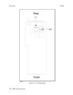
2.
Remove
the
two
screws
which
fasten
the
cover
to
the
chassis
rear
panel.
3.
Slide
the
cover
toward
the
rear
while
holding
the
front
panel
bezel.
Handler
Interface
Installation
B-5
Summary of Contents for 4339B
Page 10: ......
Page 18: ... ᄌᦝ 0123 45 6789 8 A B C ᄌᦝ 3 DE FG H FG IJ B C K 9 C Copyright 2007 Agilent Technologies ...
Page 20: ......
Page 21: ......
Page 22: ......
Page 24: ......
Page 25: ......
Page 26: ......
Page 30: ......
Page 44: ......
Page 55: ...4339B Initial Inspection Figure 1 1 Power Cable Supplied Getting Started 1 11 ...
Page 212: ......
Page 220: ......
Page 230: ......
Page 256: ......
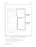
Page 268: ...Procedure 4339B Figure B 5 A1 Main Board B 8 Handler Interface Installation ...


