


4339B
Measuring
Insulation
Resistance
Time
Characteristics
Measuring
Insulation
Resistance
Time
Characteristics
of
Electro-Mechanical
Components
This
section
provides
an
example
of
measuring
electro-mechanical
components
like
switches
,
connectors
,
or
relays
.
This
example
measures
insulation
resistance
(IR)
time
characteristics
of
opened
switch
contacts
using
the
continuous
measurement
sequence
mode
,
to
obtain
time
characteristics
.
In
this
example
,
we
measure
the
insulation
resistance
of
opened
switch
DUT
,
and
measurement
data
to
printer
.
W
e
take
a
measurement
every
10
seconds
for
10
minutes
after
a
charge
time
of
60
seconds
.
W
arning
Do
NO
T
touch
the
UNKNO
WN
terminals
or
the
electrodes
of
the
accessory
,
when
the
High
V
oltage
indicator
is
ON,
the
4339B
outputs
dangerous
voltage
levels
up
to
1000
Vdc.
Before
handling
the
4339B
or
the
accessory
,
turn
OFF
the
test
voltage
pressing
and
conrm
that
the
High
V
oltage
indicator
is
OFF
.
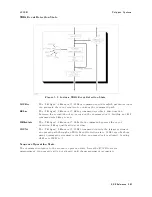
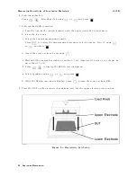
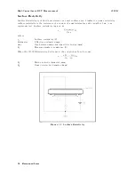
1.
Connect
the
shunt
connector
and
the
16339A
to
the
4339B ,
and
connect
the
printer
using
an
GPIB
cable
.
(F
or
the
16339A,
use
the
Alligator
Clip
and
Flat
T
able
Conguration
as
shown
in
the
16339A
Operation
and
Service
Manual.
Figure
6-5.
Measurement
Conguration
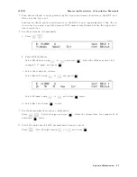
2.
Set
the
printer
to
the
Listen
Always
mode
.
3.
Reset
the
4339B
Press
to
display
the
reset
menu.
Select
Yes
using
or
and
press
.
4.
Set
the
test
voltage
value
.
Press
.
Enter
the
voltage
value
,
for
example
500
(V),
Press
.
Application
Measurement
6-9
Summary of Contents for 4339B
Page 10: ......
Page 18: ... ᄌᦝ 0123 45 6789 8 A B C ᄌᦝ 3 DE FG H FG IJ B C K 9 C Copyright 2007 Agilent Technologies ...
Page 20: ......
Page 21: ......
Page 22: ......
Page 24: ......
Page 25: ......
Page 26: ......
Page 30: ......
Page 44: ......
Page 55: ...4339B Initial Inspection Figure 1 1 Power Cable Supplied Getting Started 1 11 ...
Page 212: ......
Page 220: ......
Page 230: ......
Page 256: ......
Page 268: ...Procedure 4339B Figure B 5 A1 Main Board B 8 Handler Interface Installation ...


