


If
Y
ou
Have
a
Problem
4339B
If
Y
ou
Have
a
Problem
If
the
Display
is
Blank
and
the
4339B
Appears
Dead
If
the
display
is
blank,
and
even
the
annunciators
are
not
ON:
Check
the
fuse
.
If
an
Error
Message
is
Displayed
Refer
to
\Messages
."
If
the
4339B
does
not
A
ccept
Any
K
ey
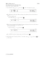
Input
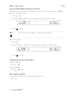
Check
whether
the
Rmt
annunciator(
9
)
is
ON.
Check
whether
the
external
controller
is
disabling
all
the
front-panel
controls
using
the
LOCAL
LOCKOUT
command.
If
so
,
send
the
LOCAL
command
from
the
external
controller
.
Press
.
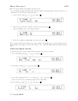
Check
whether
the
K
ey
Lock
annunciator(
9
)
is
ON.
Check
whether
the
handler
or
the
16064B
LED
display/trigger
box
is
connected
to
the
4339B
and
it
locks
out
the
keys
.
If
so
,
unlock
the
keys
from
the
handler
or
the
16064B
.
Press
.
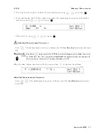
If
the
Indicated
V
alue
is
not
Stable
Shield
the
DUT
to
reduce
the
unwanted
noise
and
the
eect
of
operator
proximity
.
F
or
example
,
use
the
16339A
Component
T
est
Fixture
.
Do
not
move
the
test
leads
while
measuring.
Changing
the
position
of
the
test
leads
may
cause
noise
inside
the
test
leads
.
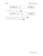
P
osition
the
4339B
on
a
stable
place
,
where
it
will
not
be
aected
by
vibration.
Vibrating
the
4339B
may
cause
noise
inside
the
4339B.
Measurement
value
could
vary
in
the
case
of
faulty
powre
line
frequency
settings
.
Refer
to
the
\
Turning
ON
the
4339B"
in
Chapter
1
to
set
the
powre
line
frequency
.
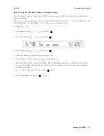
If
Y
ou
Find
Y
ourself
Lost
When
Operating
the
4339B
Press
until
the
4339B
returns
to
the
measurement
mode
.
Or
press
to
return
to
the
default
settings
.
2-22
Operating
the
4339B
Summary of Contents for 4339B
Page 10: ......
Page 18: ... ᄌᦝ 0123 45 6789 8 A B C ᄌᦝ 3 DE FG H FG IJ B C K 9 C Copyright 2007 Agilent Technologies ...
Page 20: ......
Page 21: ......
Page 22: ......
Page 24: ......
Page 25: ......
Page 26: ......
Page 30: ......
Page 44: ......
Page 55: ...4339B Initial Inspection Figure 1 1 Power Cable Supplied Getting Started 1 11 ...
Page 212: ......
Page 220: ......
Page 230: ......
Page 256: ......
Page 268: ...Procedure 4339B Figure B 5 A1 Main Board B 8 Handler Interface Installation ...


