


4339B
Front
P
anel
Trigger
K
ey
The
trigger
key
triggers
a
measurement
when
the
4339B
is
in
the
Manual
trigger
mode
.
Refer
to
\Trigger
Mode
Key
"
for
more
information.
W
arning
When
the
measurement
sequence
mode
is
ON,
pressing
may
cause
the
4339B
to
output
dangerous
voltage
levels
up
to
1000
Vdc.
Do
NO
T
touch
the
UNKNO
WN
terminals
or
the
electrodes
of
the
accessory
when
the
V
Output
indicator
is
ON.
Sequence
Abort
K
ey
The
Sequence
Abort
key
aborts
the
running
measurement
sequence
program.
Local
K
ey
The
Local
key
returns
the
4339B
to
local
(front-panel)
operation
from
GPIB
remote
(computer
controlled)
operation.
The
Local
key
is
the
only
active
front-panel
key
while
the
4339B
is
in
GPIB
remote
mode
.
When
the
4339B
is
remote
state
,
the
Rmt
annunciator(
9
)
will
be
displayed.
A
ddress
K
ey
The
A
ddress
key
sets
the
4339B 's
GPIB
address
.
The
available
GPIB
address
is
any
integer
number
from
0
to
30,
and
address
31
is
the
T
alk
Only
mode
in
which
the
4339B
only
outputs
data
through
GPIB
interface
.
Resetting
or
powering
o
doesn't
aect
the
4339B 's
address
setting.
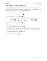
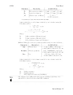
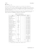
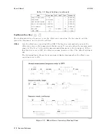
<stat>
Measured
Status
0
:
Normal
1
:
Overload
2
:
No-Contact
4
:
Over
voltage
(exceeding
ccurrent
limit)
<data>
Measured
data
<comp>
Comparison
result
(no
output
when
the
comparator
function
is
OFF)
1
:
IN
2
:
HIGH
4
:
LOW
8
:
No-Contact
System
reset
or
power-on
don't
aect
the
address
setting.
Function
Reference
3-11
Summary of Contents for 4339B
Page 10: ......
Page 18: ... ᄌᦝ 0123 45 6789 8 A B C ᄌᦝ 3 DE FG H FG IJ B C K 9 C Copyright 2007 Agilent Technologies ...
Page 20: ......
Page 21: ......
Page 22: ......
Page 24: ......
Page 25: ......
Page 26: ......
Page 30: ......
Page 44: ......
Page 55: ...4339B Initial Inspection Figure 1 1 Power Cable Supplied Getting Started 1 11 ...
Page 212: ......
Page 220: ......
Page 230: ......
Page 256: ......
Page 268: ...Procedure 4339B Figure B 5 A1 Main Board B 8 Handler Interface Installation ...


