


4339B
D
A
T
A
Subsystem
D
A
T
A
Subsystem
The
D
A
T
A
subsystem
is
used
to
store
data
to
the
4339B 's
data
buer
and
to
read
data
in
the
data
buer
.
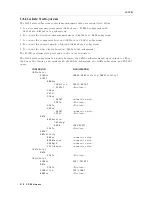
COMMAND
P
ARAMETER
DATA
[:DATA ]
REF ,<numeric
value>
[:DATA ]?
DBUF ,
IMON ,
TMON
:FEED
DBUF ,<data
handle>
:CONTrol
DBUF ,f ALWays jNEVer g
:POINts
DBUF ,<numeric
value>
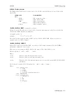
:D
A
T
A[:D
A
T
A]
REF
,<numeric
value>
Enters
or
queries
the
reference
value
for
the
deviation
measurement,
which
is
controlled
by
:CALCulate:MATH
subsystem
commands
.
<numeric
value>
is
,
numeric
09.9210
37
to
9.9210
37
The
query
form
requires
parameter
REF ,
such
as
:DATA[:DATA]?REF .
Query
response
is
a
numeric
value
in
<NR3>
format.
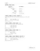
:D
A
T
A[:D
A
T
A]?
DBUF
Returns
the
data
in
data
buer
,
DBUF ,
according
to
the
format
determined
by
the
FORMat
subsystem
commands
.
(query
only)
This
query
needs
parameter
DBUF
which
is
the
name
of
the
data
buer
to
read.
Query
response
is
,
<set1>,<set2> ,
.
.
.
<setn>
Where
,
<set1>
:
Data
set
of
the
rst
measurement
point
<set2>
:
Data
set
of
the
second
measurement
point
.
.
.
<setn>
:
Data
set
of
the
last
measurement
point
(n
is
specied
using
DATA:POINts
DBUF
command)
Each
data
set
consists
of
the
following
data:
<stat>,<data>,<comp>
Where
,
<stat>
Measured
status
0
:
Normal
1
:
Overload
2
:
No-contact
4
:
Over-current
(exceeding
current
limit)
<data>
Measured
data
<comp>
Comparison
result
0
:
Comparator
o
1
:
In
2
:
High
4
:
Low
8
:
No-contact
GPIB
Reference
5-17
Summary of Contents for 4339B
Page 10: ......
Page 18: ... ᄌᦝ 0123 45 6789 8 A B C ᄌᦝ 3 DE FG H FG IJ B C K 9 C Copyright 2007 Agilent Technologies ...
Page 20: ......
Page 21: ......
Page 22: ......
Page 24: ......
Page 25: ......
Page 26: ......
Page 30: ......
Page 44: ......
Page 55: ...4339B Initial Inspection Figure 1 1 Power Cable Supplied Getting Started 1 11 ...
Page 212: ......
Page 220: ......
Page 230: ......
Page 256: ......
Page 268: ...Procedure 4339B Figure B 5 A1 Main Board B 8 Handler Interface Installation ...


