


4339B
Front
P
anel
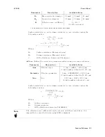
LINE
Switch
The
LINE
Switch
turns
the
4339B
ON
or
OFF
.
In
the
1
(ON)
position
power
is
applied
and
all
operating
voltages
are
applied
to
the
instrument.
In
the
0
(OFF)
position
no
power
is
applied
and
no
operating
voltages
are
applied
to
the
instrument.
The
4339B's
settings
are
held
in
backup
memory
for
about
72
hours
after
power
is
turned
OFF
.
Refer
to
\Reset
Key
"
for
the
backed
up
settings
.
Note
V
Output
ON
/OFF
state
is
not
saved,
and
the
4339B
sets
the
V
Output
to
OFF
at
power-on.
Note
If
you
turn
the
4339B
OFF
and
then
quickly
ON
again,
it
can
cause
an
error
and
the
4339B
may
not
work
normally
.
T
o
prevent
this
,
wait
for
at
least
1
second
before
turning
ON
again.
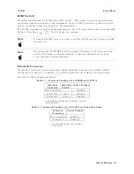
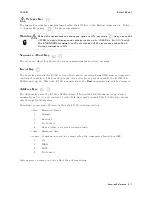
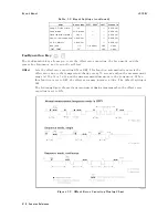
Interlock
Connector
The
4339B's
Interlock
Connector
provides
safety
from
high
voltages
and
identies
which
test
xture
is
connected.
It
enables
which
applies
the
test
voltage
to
the
test
xture
,
according
to
the
following
two
tables
.
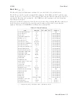
T
able
3-1.
Interlock
Condition
for
16008B
and
16339A
Interlock
Connector
Interlock
Switch
1
Source
V
oltage
Not
connected
|
Disabled
Connected
Open
Disabled
Connected
Closed
Enabled
1
The
condition
whether
the
test
xture's
cover
is
open
or
closed.
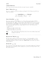
T
able
3-2.
Interlock
Condition
for
16117B
Low
Noise
T
est
Leads
Interlock
Connector
Source
V
oltage
Not
connected
Disabled
Connected
Enabled
1
1
The
available
current
limit
setting
is
0.5
mA
only
.
Function
Reference
3-3
Summary of Contents for 4339B
Page 10: ......
Page 18: ... ᄌᦝ 0123 45 6789 8 A B C ᄌᦝ 3 DE FG H FG IJ B C K 9 C Copyright 2007 Agilent Technologies ...
Page 20: ......
Page 21: ......
Page 22: ......
Page 24: ......
Page 25: ......
Page 26: ......
Page 30: ......
Page 44: ......
Page 55: ...4339B Initial Inspection Figure 1 1 Power Cable Supplied Getting Started 1 11 ...
Page 212: ......
Page 220: ......
Page 230: ......
Page 256: ......
Page 268: ...Procedure 4339B Figure B 5 A1 Main Board B 8 Handler Interface Installation ...


