


4339B
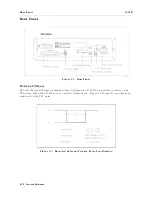
Rear
P
anel
T
able
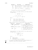
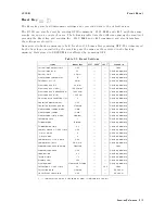
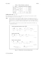
3-4.
Contact
Assignment
for
Comparator
Function
Pin
No
.
Signal
Name
1
Description
1
2
EXT
DCV1
EXT
DCV1
External
DC
V
oltage
1:
DC
voltage
supply
pins
for
DC
isolated
open
collector
outputs
(/HI,
/IN/,
/LO/,
/NO
CONT
A
CT).
Maximum
voltage
is
+24
V
,
minimum
+5
17
/HV
OFF
V
oltage
Source
OFF:
When
this
line
is
asserted,
output
of
the
voltage
source
is
disabled.
18
/KEY
LOCK
Key
Lock:
When
this
line
is
asserted,
all
of
the
4339B
's
front
panel
key
functions
are
disabled.
19
/EXT
TRIG
External
Trigger:
4339B
is
triggered
on
the
rising
edge
of
a
pulse
applied
to
this
pin
when
the
trigger
mode
is
set
to
the
External.
2
20
21
EXT
DCV2
EXT
DCV2
External
DC
voltage
2:
DC
voltage
supply
pins
for
DC
Isolated
inputs
(/EXT
TRIG,
/KEY
LOCK,
/HV
OFF)
and
DC
Isolated
outputs
(/INDEX,
/EOM,
/NOT
READY
,
/ALARM).
Maximum
voltage
is
+15
V
,
minimum
+5
V
24
25
+5
V
+5
V
Internal
voltage
supply
(max.
output
0.1
A):
Exceeding
0.1
A
will
cause
the
internal
voltage
output
and
the
output
signals
to
got
to
zero
.
26
27
COM1
COM1
Common
for
EXT
DCV1
28
/HI
This
signal
is
asserted,
when
the
comparison
result
is
High.
3
29
/IN
This
signal
is
asserted,
when
the
comparison
result
is
In.
3
30
/LO
This
signal
is
asserted,
when
the
comparison
result
is
Low
.
3
37
/NO
CONT
A
CT
This
signal
is
asserted,
when
the
contact
check
failed.
3
41
/NOT
READY
Not
ready:
This
signal
is
asserted
when
the
current
owing
through
the
DUT
exceeds
the
current
limit.
42
/ALARM
Alarm:
This
signal
is
asserted
when
a
power
failure
occurs
or
the
error
(E11,
E12,
E13,
E14,
E15,
E20
or
E-313 )
occurs
.
43
/INDEX
Index:
This
signal
is
asserted
when
an
analog
measurement
is
complete
and
the
4339B
is
ready
for
the
next
DUT
to
be
connected
to
the
UNKNOWN
terminals
.
The
measurement
data,
however
,
is
not
valid
until
/EOM
is
asserted.
44
/EOM
End
of
Measurement:
This
signal
is
asserted
when
the
measurement
data
and
comparison
results
are
valid.
45
46
COM2
COM2
Common
for
EXT
DCV2
49
50
GND
GND
Ground
tied
to
chassis
.
1
The
/
(slash)
means
that
the
signal
is
asserted
when
low
.
2
If
an
error
occurs
and
the
4339B
stops
operation,
the
4339B
will
not
trigger
a
measurement
after
receiving
the
/EXT
TRIG
signal.
3
If
an
error
occurs
and
the
4339B
stops
operation,
these
lines
maintain
the
condition
just
before
the
error
occurred.
Function
Reference
3-23
Summary of Contents for 4339B
Page 10: ......
Page 18: ... ᄌᦝ 0123 45 6789 8 A B C ᄌᦝ 3 DE FG H FG IJ B C K 9 C Copyright 2007 Agilent Technologies ...
Page 20: ......
Page 21: ......
Page 22: ......
Page 24: ......
Page 25: ......
Page 26: ......
Page 30: ......
Page 44: ......
Page 55: ...4339B Initial Inspection Figure 1 1 Power Cable Supplied Getting Started 1 11 ...
Page 212: ......
Page 220: ......
Page 230: ......
Page 256: ......
Page 268: ...Procedure 4339B Figure B 5 A1 Main Board B 8 Handler Interface Installation ...


