


4339B
Trigger
System
Trigger
System
This
section
provides
information
about
the
trigger
system
of
the
4339B.
SCPI
denes
a
common
trigger
model
for
several
types
of
instruments
.
The
trigger
system
allows
you
to
have
specic
control
of
your
measurements
.
Information
on
the
trigger
system
requires
more
technical
expertise
than
most
other
topics
covered
in
this
chapter
.
But
you
can
avoid
having
to
learn
the
information
in
this
section
by
using
the
:INITiate
commands
to
make
your
measurements
.
4339B
Trigger
System
Conguration
The
trigger
system
synchronizes
the
4339B
measurement
with
specied
events
.
Events
include
GPIB
trigger
command
or
input
pulse
on
Ext
Trigger
terminal.
The
trigger
system
also
allows
you
to
specify
the
number
of
times
to
repeat
a
measurement
and
the
delays
between
measurements
.
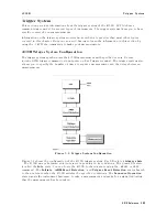
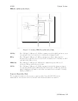
Figure
5-6.
Trigger
System
Conguration
Figure
5-6
shows
the
conguration
of
the
4339B
trigger
system.
Each
block
is
a
trigger
state
.
The
4339B
moves
between
adjacent
states
depending
on
its
conditions
.
The
power
ON
state
is
called
the
Idle
state
.
Y
ou
can
force
the
4339B
to
the
idle
state
using
the
:ABORt
or
*RST
command.
The
Initiate
,
ARM
Event
Detection
,
and
Trigger
Event
Detection
states
branch
to
the
next
state
when
the
4339B
satises
the
specied
conditions
.
The
Sequence
Operation
state
signals
the
instrument
hardware
to
take
a
measurement
and
waits
for
a
signal
indicating
that
the
measurement
has
been
taken.
GPIB
Reference
5-45
Summary of Contents for 4339B
Page 10: ......
Page 18: ... ᄌᦝ 0123 45 6789 8 A B C ᄌᦝ 3 DE FG H FG IJ B C K 9 C Copyright 2007 Agilent Technologies ...
Page 20: ......
Page 21: ......
Page 22: ......
Page 24: ......
Page 25: ......
Page 26: ......
Page 30: ......
Page 44: ......
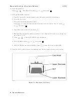
Page 55: ...4339B Initial Inspection Figure 1 1 Power Cable Supplied Getting Started 1 11 ...
Page 212: ......
Page 220: ......
Page 230: ......
Page 256: ......
Page 268: ...Procedure 4339B Figure B 5 A1 Main Board B 8 Handler Interface Installation ...


