


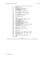


4339B
Sample
Program
400
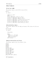
OUTPUT
@Hp4339;":CALC:RES:EAR
0.0019635"
410
OUTPUT
@Hp4339;":CALC:RES:EPER
0.18850"
420
OUTPUT
@Hp4339;":CALC:RES:GLEN
0.01"
430
!
440
OUTPUT
@Hp4339;":SENS:FUNC
'RES'"
450
DISP
"Turn
the
Volume/Surface
selector
to
`Volume'."
460
PAUSE
470
DISP
480
OUTPUT
@Hp4339;":CALC:FORM
VRES"
490
OUTPUT
@Hp4339;"*TRG"
500
ENTER
@Hp4339;S,D
510
"Volume
Resistivity:",D;"[OHMcm]","Status:";S
520
!
530
DISP
"Turn
the
Volume/Surface
selector
to
`Surface'."
540
PAUSE
550
DISP
560
OUTPUT
@Hp4339;":CALC:FORM
SRES"
570
OUTPUT
@Hp4339;"*TRG"
580
ENTER
@Hp4339;S,D
590
"Surface
Resistivity:",D;"[OHM]","Status:";S
600
END
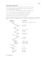
Figure
4-8.
Sample
Program
Lines
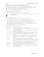
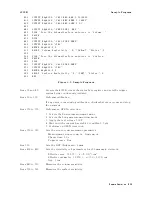
30
and
40
Presets
the
4339B ,
clears
the
status
byte
register
,
and
sets
the
trigger
system
being
continuously
initiated.
Lines
60
to
130
P
erforms
calibration.
If
any
error
occurs
during
calibration,
check
what
error
occurs
and
stop
the
program.
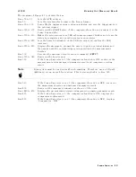
Lines
150
to
330
P
erforms
an
OPEN
correction:
1.
Selects
the
Current
measurement
mode
.
2.
Selects
the
Long
measurement
time
mode
.
3.
Apply
the
test
voltage
,
500
V
.
4.
W
ait
until
the
current
has
stabled
to
within
0.5
pA.
5.
P
erforms
an
OPEN
correction.
Lines
350
to
370
Sets
the
sequence
measurement
parameter:
Measurement
sequence
mode:
Single
mode
Charge
time:
60
s
Trigger
source:
Bus
Line
390
Sets
the
DUT
thickness
to
2
mm.
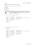
Lines
400
to
420
Sets
the
resistivity
cell
parameters
for
50
mm
main
electrode:
Eective
area:
19.635
(=
2(5.0/2)
2
)
cm
2
Eective
perimeter:
18.850
(=
2(5.0+7.0)/2)
cm
Gap:
1
cm
Lines
440
to
510
Measures
the
volume
resistivity
.
Lines
530
to
590
Measures
the
surface
resistivity
.
Remote
Operation
4-29
Summary of Contents for 4339B
Page 10: ......
Page 18: ... ᄌᦝ 0123 45 6789 8 A B C ᄌᦝ 3 DE FG H FG IJ B C K 9 C Copyright 2007 Agilent Technologies ...
Page 20: ......
Page 21: ......
Page 22: ......
Page 24: ......
Page 25: ......
Page 26: ......
Page 30: ......
Page 44: ......
Page 55: ...4339B Initial Inspection Figure 1 1 Power Cable Supplied Getting Started 1 11 ...
Page 212: ......
Page 220: ......
Page 230: ......
Page 256: ......
Page 268: ...Procedure 4339B Figure B 5 A1 Main Board B 8 Handler Interface Installation ...


