


Figures
1-1.
P
ower
Cable
Supplied
.
.
.
.
.
.
.
.
.
.
.
.
.
.
.
.
.
.
.
.
.
.
.
.
.
.
.
1-11
1-2.
Floating
DUT
Measurement
Conguration
.
.
.
.
.
.
.
.
.
.
.
.
.
.
.
.
.
.
1-19
1-3.
Grounded
DUT
Measurement
Conguration
.
.
.
.
.
.
.
.
.
.
.
.
.
.
.
.
.
1-19
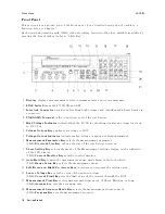
3-1.
Front
P
anel
.
.
.
.
.
.
.
.
.
.
.
.
.
.
.
.
.
.
.
.
.
.
.
.
.
.
.
.
.
.
.
.
3-2
3-2.
Sequence
Mode
.
.
.
.
.
.
.
.
.
.
.
.
.
.
.
.
.
.
.
.
.
.
.
.
.
.
.
.
.
.
3-6
3-3.
Oset-Error
Canceling
Timing
Chart
.
.
.
.
.
.
.
.
.
.
.
.
.
.
.
.
.
.
.
.
3-18
3-4.
Rear
P
anel
.
.
.
.
.
.
.
.
.
.
.
.
.
.
.
.
.
.
.
.
.
.
.
.
.
.
.
.
.
.
.
.
3-20
3-5.
Required
External
Trigger
Pulse
Specication
.
.
.
.
.
.
.
.
.
.
.
.
.
.
.
.
3-20
3-6.
Pin
Assignment
for
Handler
Interface
Connector
.
.
.
.
.
.
.
.
.
.
.
.
.
.
.
3-22
3-7.
Timing
Diagram
.
.
.
.
.
.
.
.
.
.
.
.
.
.
.
.
.
.
.
.
.
.
.
.
.
.
.
.
.
.
3-24
3-8.
Simplied
Model
of
Impedance
Measurement
.
.
.
.
.
.
.
.
.
.
.
.
.
.
.
.
3-26
3-9.
4339B
Overall
Block
Diagram
.
.
.
.
.
.
.
.
.
.
.
.
.
.
.
.
.
.
.
.
.
.
.
.
3-27
3-10.
Ungrounded
and
Grounded
DUT
Measurement
.
.
.
.
.
.
.
.
.
.
.
.
.
.
.
3-28
4-1.
Simple
Program
Example
.
.
.
.
.
.
.
.
.
.
.
.
.
.
.
.
.
.
.
.
.
.
.
.
.
.
4-4
4-2.
SRQ
generation
sequence
(when
measurement
nishes)
.
.
.
.
.
.
.
.
.
.
.
4-12
4-3.
Detecting
the
completion
of
measurement
using
SRQ
.
.
.
.
.
.
.
.
.
.
.
.
.
4-13
4-4.
Reading
out
the
measured
result
in
ASCII
transfer
format
by
using
the
*TRG
command
.
.
.
.
.
.
.
.
.
.
.
.
.
.
.
.
.
.
.
.
.
.
.
.
.
.
.
.
.
.
.
4-16
4-5.
Reading
out
the
measured
result
in
binary
transfer
format
using
*TRG
command
4-18
4-6.
Reading
out
the
measured
result
in
ASCII
transfer
format
using
the
:FETC?
command
.
.
.
.
.
.
.
.
.
.
.
.
.
.
.
.
.
.
.
.
.
.
.
.
.
.
.
.
.
.
.
4-20
4-7.
Reading
out
measured
result
in
binary
transfer
format
using
:FETC?
command
4-22
4-8.
Sample
Program
.
.
.
.
.
.
.
.
.
.
.
.
.
.
.
.
.
.
.
.
.
.
.
.
.
.
.
.
.
.
4-29
5-1.
Proper
Use
of
the
Colon
and
Semicolon
.
.
.
.
.
.
.
.
.
.
.
.
.
.
.
.
.
.
.
5-2
5-2.
Status
Reporting
Structure
.
.
.
.
.
.
.
.
.
.
.
.
.
.
.
.
.
.
.
.
.
.
.
.
.
5-40
5-3.
Status
byte
Register
.
.
.
.
.
.
.
.
.
.
.
.
.
.
.
.
.
.
.
.
.
.
.
.
.
.
.
.
5-41
5-4.
Standard
Event
Status
Register
.
.
.
.
.
.
.
.
.
.
.
.
.
.
.
.
.
.
.
.
.
.
.
5-42
5-5.
Standard
Operation
Status
Group
Structure
.
.
.
.
.
.
.
.
.
.
.
.
.
.
.
.
.
5-43
5-6.
Trigger
System
Conguration
.
.
.
.
.
.
.
.
.
.
.
.
.
.
.
.
.
.
.
.
.
.
.
.
5-45
5-7.
Inside
an
ARM
Event
Detection
State
.
.
.
.
.
.
.
.
.
.
.
.
.
.
.
.
.
.
.
.
5-46
5-8.
Inside
a
TRIG
Event
Detection
State
.
.
.
.
.
.
.
.
.
.
.
.
.
.
.
.
.
.
.
.
5-47
5-9.
NR1
F
ormat
.
.
.
.
.
.
.
.
.
.
.
.
.
.
.
.
.
.
.
.
.
.
.
.
.
.
.
.
.
.
.
.
5-48
5-10.
NR2
F
ormat
.
.
.
.
.
.
.
.
.
.
.
.
.
.
.
.
.
.
.
.
.
.
.
.
.
.
.
.
.
.
.
.
5-48
5-11.
NR3
F
ormat
.
.
.
.
.
.
.
.
.
.
.
.
.
.
.
.
.
.
.
.
.
.
.
.
.
.
.
.
.
.
.
.
5-48
5-12.
Real
Data
F
ormat
.
.
.
.
.
.
.
.
.
.
.
.
.
.
.
.
.
.
.
.
.
.
.
.
.
.
.
.
.
5-49
6-1.
Measurement
Conguration
.
.
.
.
.
.
.
.
.
.
.
.
.
.
.
.
.
.
.
.
.
.
.
.
6-2
6-2.
Chip
Capacitor
Binding
.
.
.
.
.
.
.
.
.
.
.
.
.
.
.
.
.
.
.
.
.
.
.
.
.
.
.
6-3
6-3.
Measurement
Conguration
.
.
.
.
.
.
.
.
.
.
.
.
.
.
.
.
.
.
.
.
.
.
.
.
6-5
6-4.
Resistivity
Cell
Setup
.
.
.
.
.
.
.
.
.
.
.
.
.
.
.
.
.
.
.
.
.
.
.
.
.
.
.
6-6
6-5.
Measurement
Conguration
.
.
.
.
.
.
.
.
.
.
.
.
.
.
.
.
.
.
.
.
.
.
.
.
6-9
6-6.
Clipping
Opened
Switch
.
.
.
.
.
.
.
.
.
.
.
.
.
.
.
.
.
.
.
.
.
.
.
.
.
.
6-10
6-7.
Printed
Results
.
.
.
.
.
.
.
.
.
.
.
.
.
.
.
.
.
.
.
.
.
.
.
.
.
.
.
.
.
.
6-11
7-1.
V
olume
Resistivity
.
.
.
.
.
.
.
.
.
.
.
.
.
.
.
.
.
.
.
.
.
.
.
.
.
.
.
.
.
7-3
7-2.
Surface
Resistivity
.
.
.
.
.
.
.
.
.
.
.
.
.
.
.
.
.
.
.
.
.
.
.
.
.
.
.
.
.
7-4
7-3.
Capacitance
Measurement
Conguration
.
.
.
.
.
.
.
.
.
.
.
.
.
.
.
.
.
.
7-7
9-1.
Source
V
oltage
A
ccuracy
T
est
Setup
.
.
.
.
.
.
.
.
.
.
.
.
.
.
.
.
.
.
.
.
.
9-4
Contents-11
Summary of Contents for 4339B
Page 10: ......
Page 18: ... ᄌᦝ 0123 45 6789 8 A B C ᄌᦝ 3 DE FG H FG IJ B C K 9 C Copyright 2007 Agilent Technologies ...
Page 20: ......
Page 21: ......
Page 22: ......
Page 24: ......
Page 25: ......
Page 26: ......
Page 30: ......
Page 44: ......
Page 55: ...4339B Initial Inspection Figure 1 1 Power Cable Supplied Getting Started 1 11 ...
Page 212: ......
Page 220: ......
Page 230: ......
Page 256: ......
Page 268: ...Procedure 4339B Figure B 5 A1 Main Board B 8 Handler Interface Installation ...


