84 Control panels
Copy mode
The basic control panel can store a full set of drive parameters and up to three user
sets of drive parameters to the control panel. Uploading and downloading can be
performed in local control. The control panel memory is non-volatile.
In the Copy mode, you can do the following:
• Copy all parameters from the drive to the control panel (uL – Upload). This
includes all defined user sets of parameters and internal (not adjustable by the
user) parameters such as those created by the ID run.
• Restore the full parameter set from the control panel to the drive (dL A –
Download all). This writes all parameters, including the internal non-user-
adjustable motor parameters, to the drive. It does not include the user sets of
parameters.
Note:
Only use this function to restore a drive, or to transfer parameters to
systems that are identical to the original system.
• Copy a partial parameter set from the control panel to a drive (dL P – Download
partial). The partial set does not include user sets, internal motor parameters,
parameters
,
,
, nor any group
parameters.
The source and target drives and their motor sizes do not need to be the same.
• Copy user set 1 parameters from the control panel to the drive (dL u1 – Download
user set 1). A user set includes group
parameters and the
internal motor parameters.
The function is only shown on the menu when user set 1 has been first saved
using parameter
(see section
on page
and then uploaded to panel.
• Copy user set 2 parameters from the control panel to the drive (dL u2 – Download
user set 2). As dL u1 – Download user set 1 above.
• Copy user set 3 parameters from the control panel to the drive (dL u3 – Download
user set 2). As dL u1 – Download user set 1 above.
• Start, stop, change the direction and switch between local and remote control.
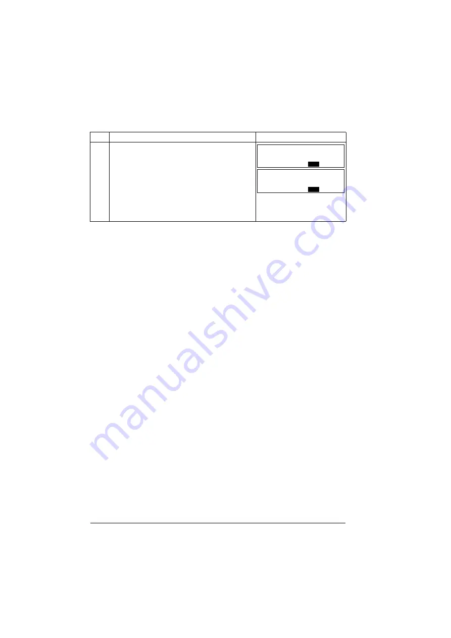
4.
Select the scalings for the signals by specifying the
minimum and maximum display values. This has no
effect if parameter
is set to 9
). For details, see parameters
and
.
Signal 1: parameters
and
Signal 2: parameters
and
Signal 3: parameters
and
Step Action
Display
LOC
Hz
PAR
SET
FWD
00
.
LOC
Hz
PAR
SET
FWD
5000
.
Summary of Contents for ACS355 series
Page 1: ...ABB machinery drives User s manual ACS355 drives ...
Page 4: ......
Page 16: ...16 ...
Page 32: ...32 Operation principle and hardware description ...
Page 58: ...58 Electrical installation ...
Page 74: ...74 Start up control with I O and ID run ...
Page 106: ...106 Control panels ...
Page 120: ...120 Application macros ...
Page 178: ...178 Program features ...
Page 338: ...338 Fieldbus control with embedded fieldbus ...
Page 368: ...368 Fault tracing ...
Page 404: ...404 Dimension drawings ...
Page 410: ...410 Appendix Resistor braking ...
Page 434: ...434 Appendix Permanent magnet synchronous motors PMSMs ...


