310 Actual signals and parameters
9905 MOTOR NOM
VOLT
Defines the nominal motor voltage. For asynchronous
motors, must be equal to the value on the motor rating plate.
For permanent magnet synchronous motors, the nominal
voltage is the back emf voltage at nominal speed.
If the voltage is given as voltage per rpm, eg, 60 V per
1000 rpm, the voltage for 3000 rpm nominal speed is
3 · 60 V = 180 V.
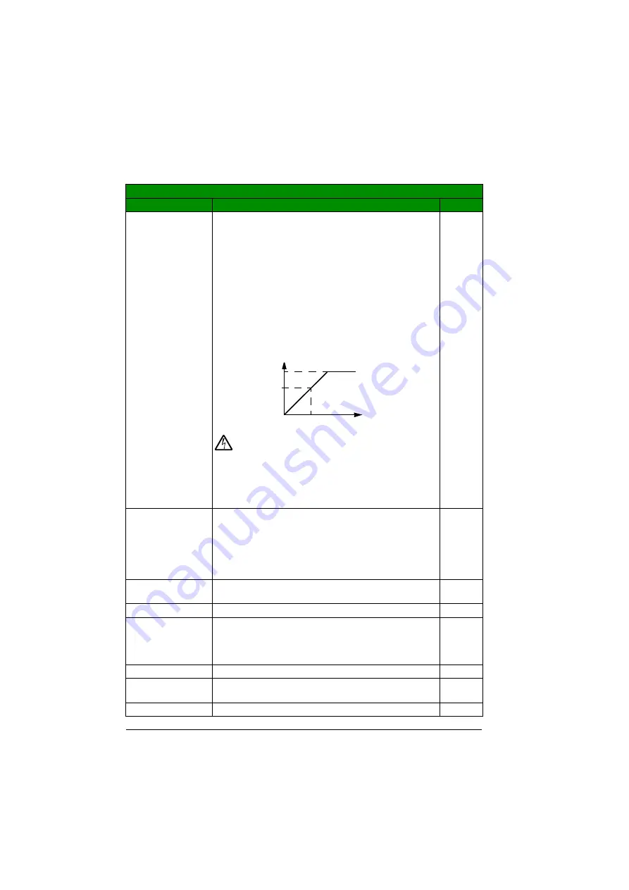
The drive cannot supply the motor with a voltage greater
than the input power voltage.
Note that the output voltage is not limited by the nominal
motor voltage but increased linearly up to the value of the
input voltage.
WARNING!
The stress on the motor insulations
depends on the drive supply voltage. This applies
also when the motor voltage rating is lower than the rating of
the drive and the supply voltage of the drive. The rms
voltage can be limited to motor nominal voltage by setting
the maximum frequency of the drive (parameter
) to the
motor nominal frequency.
200 V
units:
230 V
400 V
E units:
400 V
400 V
U units:
460 V
200 V units:
46…345 V
400 V E units:
80…600 V
400 V U units:
92…690 V
Voltage.
1 = 1 V
9906 MOTOR NOM
CURR
Defines the nominal motor current. Must be equal to the
value on the motor rating plate.
I
2N
0.2…2.0 ·
I
2N
Current
1 = 0.1 A
9907 MOTOR NOM
FREQ
Defines the nominal motor frequency, ie, the frequency at
which the output voltage equals the motor nominal voltage:
Field weakening point = Nom. frequency · Supply voltage /
Motor nom. voltage
E: 50.0 Hz
U: 60.0 Hz
0.0…599.0 Hz
Frequency
1 = 0.1 Hz
9908 MOTOR NOM
SPEED
Defines the nominal motor speed. Must be equal to the
value on the motor rating plate.
Type
dependent
50…30000 rpm Speed
1 = 1 rpm
All parameters
No.
Name/Value
Description
Def/FbEq
Output voltage
Output frequency
Input voltage
Summary of Contents for ACS355 series
Page 1: ...ABB machinery drives User s manual ACS355 drives ...
Page 4: ......
Page 16: ...16 ...
Page 32: ...32 Operation principle and hardware description ...
Page 58: ...58 Electrical installation ...
Page 74: ...74 Start up control with I O and ID run ...
Page 106: ...106 Control panels ...
Page 120: ...120 Application macros ...
Page 178: ...178 Program features ...
Page 338: ...338 Fieldbus control with embedded fieldbus ...
Page 368: ...368 Fault tracing ...
Page 404: ...404 Dimension drawings ...
Page 410: ...410 Appendix Resistor braking ...
Page 434: ...434 Appendix Permanent magnet synchronous motors PMSMs ...


