background image


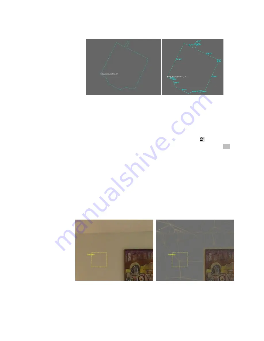
Figure 39  Outline with and without measures visible 

8.1.5


Select Region 

Certain operations require selecting a region of the range, image or model data. Selecting a 

region of data is very similar to using the outline tool – you draw an outline around the data you 

want to select.  

First pick 

Region

 from the Select menu, or the Select Region button (

) from the toolbar. 

Move the cursor to the point where you will start the outline of your region, hold 

Ctrl

 (the 

cursor will change to a pointing hand) and click on the first point. As with the outline tool, you 

will draw a point and a line will connect that point to your cursor. Move the cursor to the next 

point in the outline and click again. Continue adding points in this way. To complete the outline 

of the region, double click on your last point. This will select the last point and connect the last 

point to the first point. The selected data turns red when the selection is complete. 

The region selected will typically be larger than your outline and will have a more irregular 

outline. This is because the data is made up of triangles whose edges do not match the edge of 

your outline. If a triangle overlaps the region you outlined, the entire triangle becomes selected. 

The images in Figure 40 show a region selection, the corresponding triangles (in wire frame 

view), the selected region and its corresponding triangles. 


DeltaSphere-3000 3D Scene Digitizer 

57 


9/23/05 

Summary of Contents for DeltaSphere-3000

Page 1: ...DeltaSphere 3000 Laser 3D Scene Digitizer User Manual v3 2 Revision B 3rdTech Inc Copyright 2001 2005 3rdTech Inc 9 23 2005 3rdTech Inc ...

Page 2: ... SceneVision 3D Uses 18 7 Viewing Tools 45 3 3 1 Acquiring Data 18 7 1 Viewing Range Data 45 3 3 2 Viewing Data 19 7 2 Viewing 3D Model Data 47 3 3 3 Processing Scan Data 19 3 3 4 Data Analysis and Annotation 19 7 3 Viewing images 51 3 4 Creating a Scene 20 8 Annotation and Analysis Tools 53 3 4 1 The SceneVision Window Layout 20 8 1 Draw Measure Tools 53 3 4 2 Creating Scenes from a Scan Session ...

Page 3: ...del 89 11 4 Create Simplified Model 89 12 Editing 90 12 1 Model Editing 90 12 2 Inserting High resolution Photos 91 12 3 Making a Photo Hotspot 92 12 4 Deleting Data 92 12 5 SceneVision 3D Viewer 93 12 5 1 Installation 94 12 5 2 Data Preparation and Transfer 94 13 Menu Reference 96 13 1 File Menu 96 13 2 Edit Menu 100 13 3 Select Menu 102 13 4 View Menu 103 13 4 1 View Menu for Model Data 103 13 4...

Page 4: ... measuring the area or objects scanned and for producing 3D computer graphics models With the color option the DeltaSphere 3000 can also provide a full color value for each point as well as high resolution texture maps This manual provides information about the DeltaSphere 3000 Software installation and hardware set up Scanning operation Data viewing processing analysis and presentation NOTE The D...

Page 5: ...nd Annotation and Analysis Tools are principally for those involved with viewing and analysis of DeltaSphere data though they may be of interest to all users Sections 9 and 10 on Range Alignment and Color Alignment are primarily for those involved in data preparation They describe the alignment needed to combine multiple scans and to add color to a scan Section 11describes how to create 3D models ...

Page 6: ...ncludes a professional color digital camera and lens a special camera mount and additional software The infrared version includes one pair of laser safety glasses Figure 1 DeltaSphere 3000 3D Scene Digitizer 2 2 Physical Setup The DeltaSphere 3000 has several mounting options designed to accommodate both professional camera tripods and surveyor s tripods The DeltaSphere s base plate has three moun...

Page 7: ... rubber feet down never place it on the side with the various connectors The quick release camera mount provided is recommended for use with a photographer s tripod We recommend a heavy duty tripod with a 3 8 16 mounting screw and a geared column Figure 2 shows the base of the DeltaSphere 3000 as well as the two parts of the quick release camera mount Figure 2 DeltaSphere 3000 base plate and quick...

Page 8: ... attach the DeltaSphere 3000 to the tripod open the receiver mount by moving the release lever and safety lever as described in the quick mount instructions provided Holding the DeltaSphere securely by both handles place the base of the DeltaSphere in the mount as shown in Figure 5 with two sides of the hexagonal plate securely under the receiver s dovetail sides The DeltaSphere 3000 is not shown ...

Page 9: ...DeltaSphere NOTE Be careful to fully support the DeltaSphere 3000 at all times until you are sure it is locked into place 2 2 2 Tribrach Installation The DeltaSphere 3000 can be mounted directly onto a surveyor s tripod or onto a Tribrach adaptor using the 5 8 11 mounting hole on the base plate Once the Tribrach adaptor is mounted on the DeltaSphere 3000 it can be mounted on a standard Tribrach No...

Page 10: ...frotto 3290 Monitor Projector Platform Bogen Manfrotto 2900 Super Clamp with Standard Stud attaches to tripod leg Bogen Manfrotto 155 Double Ball Joint Head with 2933 Camera Platform attaches to Super Clamp and to the Monitor Platform These components are available from many photographic equipment suppliers as well as from 3rdTech In this section we will describe how to assemble the laptop stand 1...

Page 11: ...htening securely Figure 9 Camera Platform Added 3 Attach the Super Clamp to a tripod leg as shown in Figure 10 and tighten securely Place it low enough on the leg so that when the laptop is on the platform and the screen is open it will not interfere with the movement of the DeltaSphere You can adjust this later Figure 10 Super Clamp on Tripod Leg DeltaSphere 3000 3D Scene Digitizer 10 9 23 05 ...

Page 12: ... how the camera platform attaches to the bottom of the laptop platform without the tripod and other components in the way For the platform to be stable secure the camera platform so that it is perpendicular to the long side of the laptop platform as shown and tighten securely When done there should be very little wobble in the platform and it should easily and securely support the laptop The compl...

Page 13: ...able for both desktop and laptop PCs Viewing 3D models in particular can be very slow without one of these cards Contact 3rdTech for specific recommendations 2 3 1 Installation Procedure SceneVision software is installed from the DeltaSphere software CD Instructions for this installation follow Note You must have administrator privileges to install SceneVision 1 With your PC running put the instal...

Page 14: ...use the program The DeltaSphere 3000 User Manual this document is in the file Delta_Manual_v3 0a pdf To open the file either go to the Start menu and select Programs DeltaSphere DeltaSphere 3000 User Manual or run SceneVision 3D and select Help from the program s Help menu Display Setting SceneVision 3D requires running your display in 24 bit or 32 bit mode SceneVision will not run without one of ...

Page 15: ...ich is supplied between the scanner and a PC a connection through a private hub or a connection through a larger network each of the latter with a standard Ethernet cable not supplied The DeltaSphere 3000 arrives with an IP address already specified See the configuration doc printed and placed in the front of the manual for the IP address of your DeltaSphere or see the label on the scanner Unlike ...

Page 16: ... correctly connected via the Ethernet and that the IP address is correct Connecting via a private hub or network will generally be exactly the same Connect the DeltaSphere to the hub or network with a standard Ethernet cable not the supplied crossover cable Then run SceneVision from a client PC on the same network or hub Occasionally the default IP address assigned to your DeltaSphere will need to...

Page 17: ...y the users The three principal kinds of data are described below Range Data Range data is the raw data produced by the DeltaSphere 3000 Scanner It consists of a long list of 3D points typically millions of points These points are described by their position when scanned and by the intensity of the laser s reflection Each point is described by 4 numbers Range the distance of the point from the sca...

Page 18: ...IFF tif BMP bmp and PNG png Photo data is 2D Note We ll use the terms image data and photo interchangeably in this document Model Data Model data is produced by connecting the points in range data to form triangles a triangular mesh These triangles form a 3D surface of the scanned objects The triangles can either be colored by the laser intensity in which case they will be shaded with a grayscale ...

Page 19: ...g scheme and are stored with a logical file organization The general organization is A folder for the entire scene A subfolder for each scan containing the range file for that scan In each scan s subfolder another subfolder for all photos associated with that scan Figure 17 illustrates a scene composed of three scans lr_body lr_doorway lr_reference with an additional folder for freehand photos Thi...

Page 20: ...the distance from a point in one scan to a point in another You can also produce a complete 3D model from all or part of the aligned scans Color Alignment Color alignment is used to map digital photos to range data producing color range data This color range data can then be used to create color 3D models SceneVision provides the tools for color alignment See section 10 Model Creation and Editing ...

Page 21: ...a look at the SceneVision window When you run SceneVision the window will look like Figure 18 It is divided into several sections Figure 18 SceneVision window Near the top left are five menus File Edit View Window and Help Additional menus appear when data windows are opened Below the menus are tabs which provide four main categories of functions DeltaSphere control is through the Scan tab Most vi...

Page 22: ...o the SceneVision window Note If you try to open an image file the program will assign to this photo the default camera configuration file DeltaSphere 3000 cameras are calibrated and have associated configuration files cfg This enables the mapping of photos to the range data Each camera lens combination has its own configuration file Camera configuration files are discussed in section 10 After loa...

Page 23: ...y number of files or complete directories This is often used to process data of a single scan from a scene that has many scans With SceneVision running select New Scene from the File menu If you skip this step you will be prompted to create a scene file in the next step SceneVision 3D will create both a folder for the new scene and the new scene file Then select Insert Files or Insert Directory fr...

Page 24: ...osen is a 360 scan of the space providing a frame of reference for smaller scans of parts of the space You can either choose one of the files at this time or cancel and choose a file during the range align procedure See section 9 for additional information Adding Files It is not unusual to add files to a scene after it has been created This is done with the Insert File command in the File menu or ...

Page 25: ...e 3000IR There are no user serviceable parts Please contact 3rdTech support or your reseller for any technical difficulties Do not operate the scanner where the air temperature is more than 45ºC 113ºF Always turn the system on for at least 10 minutes before scanning Do not point the scanner at the sun or at other intense light or heat sources The DeltaSphere s sensor will operate when pointed at s...

Page 26: ...n and has had enough time to boot about 1 minute The IP Address of the DeltaSphere 3000 system see Section 2 3 3 should appear in the DeltaSphere IP address box If not enter the IP address of your DeltaSphere It can be found on a label on the face of the scanner and in your documentation See section 15 1 for setting the IP address in the configuration file Select Connect The button will turn yello...

Page 27: ...de longitude system on the surface of the earth or azimuth elevation coordinates used in surveying 4 3 1 Setting Scan Parameters Horizontal Field of View The Horizontal Field of View is set by specifying the start minimum and end maximum horizontal rotation of the scan 0º is defined to be the perpendicular view coming out from the front of the DeltaSphere the side with the DeltaSphere 3000 label s...

Page 28: ...he negative limit of the Vertical FOV is approximately 55º Below that angle the laser intersects the DeltaSphere s case The upper limit is 90º straight overhead but with the optional camera mounted the limit is approximately 75º The Vertical FOV will accept values from 55º to 90º To scan a complete panorama with the DeltaSphere typical Vertical FOV values would be 55º to 90º or 75º To eliminate an...

Page 29: ...ings Hor FOV Samples Deg Speed rev s Approximate Time 90 90 5 4 4 minutes 90 90 10 4 8 minutes 180 180 13 33 8 11 minutes 180 180 15 8 13 minutes 180 180 10 8 8 minutes 180 180 20 4 30 minutes 180 180 5 16 3 minutes Note Changing the Horizontal Field of View changes both the size of the file and the time to scan Changing the Vertical Field of View changes the size of the file but has no effect on ...

Page 30: ...he DeltaSphere 3000 the buttons pointing left will rotate the scanner counterclockwise forward the direction it scans and those on the right clockwise reverse with the actions described below W Rotate the DeltaSphere 3000 5 counterclockwise a 5 rotation will automatically stop at 360 X Rotate the DeltaSphere 3000 5 clockwise a 5 rotation will automatically stop at 360 Rotate the DeltaSphere 3000 c...

Page 31: ...change in position to prevent the scanner or camera from wobbling during acquisition See section 6 for detailed information about scanning for range and color After you have set your scan parameters cleared the area and put on safety glasses select the Start button If you have not yet created a scene you will be asked to create one as described in Section 4 2 1 or to select an existing scene All D...

Page 32: ...m different locations but in the same scene This typically involves moving the DeltaSphere and tripod to a new location Then if the scene is still open set the scan parameters once again and hit Start You will be prompted for a new scan name which will be created in the same scene directory but in its own subfolder Figure 22 SceneVision with Scan Data DeltaSphere 3000 3D Scene Digitizer 31 9 23 05...

Page 33: ... you ordered the color option at the same time as the DeltaSphere it will arrive with the base of the camera mount already installed A camera mount thumbscrew for locking the camera to the camera mount Software for controlling the camera and DeltaSphere 3000 and for mapping color image data to point clouds 5 1 2 Mounting the Camera Note This section describes the camera mount that began shipping i...

Page 34: ... as shown The receiver is designed to remain permanently attached to the DeltaSphere during use storage and shipping Figure 24 Receiver part of the camera mount Attach the Camera Bracket to the Receiver The camera bracket is designed to easily attach to the receiver for use and to detach for storage or shipping To attach remove the tee thumbscrew from the back of the bracket Slide the bracket into...

Page 35: ...emove the thumbscrew rotate the arm upward and replace the thumbscrew in the topmost of the three holes Screw in firmly Notice how the hole in the center of the cross bar of the T with the camera mounting thumbscrew is now easily accessible Note The camera mount thumbscrew can be stored in the tee shaped arm by positioning it in the upward view When in the downwar view the screw can be removed Do ...

Page 36: ...a grip is facing up the base of the camera is to the right and the lens is above the rotating mirror The bottom front of the camera should be flush against the rectangular metal stop on the rotating arm as shown in Figure 27 Place the thumbscrew through the arm and firmly screw in to the camera s tripod mount Do not release the camera until you are sure it is firmly attached Figure 27 Camera attac...

Page 37: ...structions that came with your DeltaSphere 3000 Color Option shipment 5 2 1 IEEE 1394 and Camera Driver The DeltaSphere 3000 color option uses an IEEE 1394 FireWire connection between the controller PC and the FUJIFILM camera for communication control and image acquisition Some PCs and laptops have a 1394 connection built in or it can be added with a peripheral card Fuji requires an OHCI compliant...

Page 38: ... range from each tripod position before moving the tripod to the next location It doesn t matter whether you do range or color first as long as they are both from the same tripod position 6 1 2 Adjust and Connect the Camera Note These instructions apply to the current shipping camera and lens the FujiFilm FinePix S2Pro and Nikon AF Nikkor 14mm lens Please refer to the original documentation for yo...

Page 39: ...that the 1394 connection will use up batteries very quickly Use the power supply if possible Connect the Firewire 1394 cable to the camera and to the PC laptop running SceneVision See Figure 28 Turn the camera on Do not move the tripod Do not change the settings in SceneVision the horizontal FOV settings are used by the camera operation Do not change the position of any of the objects in the scene...

Page 40: ... the current camera settings The image will be displayed in a new window as in Figure 30 Using the image displayed adjust the camera settings A histogram of the image intensity is displayed in the lower left part of the window for additional guidance in setting the correct exposure Adjust the settings and preview as often as necessary these images are not saved Figure 30 Camera Preview window Delt...

Page 41: ... range data and images are saved in files even if you don t save the scene Once range data has been scanned with the laser rangefinder and all the color images have been acquired with the digital camera the tripod can be moved to a new position Note Typically you do not need to remove the camera during scanning for range though with the camera mounted the vertical view of the laser is limited to a...

Page 42: ...re are six different ISO settings from ISO 100 to ISO 1600 which adjust the camera s sensitivity to light White Balance There are seven preset white balance settings appropriate for adjusting the color in a variety of lighting situations including daylight shade incandescent lights and several fluorescent light settings You can also select custom white balance settings created using the camera s b...

Page 43: ...e window is difficult to see because of lighting conditions 6 2 2 Auto Acquire Once the camera settings are adjusted the Auto Acq tab is used to capture the images associated with a scan With Auto Acquire the DeltaSphere automatically takes a series of images covering the horizontal field of view of the scan Once the parameters are set and the process begins no additional user intervention is requ...

Page 44: ... much easier to produce a model with uniform color Start Clicking on Start will begin the image acquisition The DeltaSphere will rotate to all the necessary positions and take the appropriate number of images at each position These images will be stored in the images folder of the scan selected Often after Auto Acquire you will want to change the position of the camera from Hi to Low or vice versa...

Page 45: ...elect New Dir and you will be prompted for a new root name and directory Note For FujiFilm S2Pro only When starting to take Manual Acquire pictures the setting for White Balance is not taken from the Camera Controls window Instead the last setting on the camera will be used If you need to match pictures taken with Auto Acquire mode change your White Balance setting to match by pressing the FUNC bu...

Page 46: ...k on the file the manual will provide a pointer to the right file in each subsection 7 1 Viewing Range Data Range data RTPI files with or without color can be viewed in a SceneVision window like the grayscale kitchen in Figure 22 Note For a sample double click on v1 rtpi in the clue scene tree After loading you can resize the window as you would any other Microsoft window Once the window is open y...

Page 47: ...or uncolored range data Show Intensity Equalized Performs histogram equalization on the display of the intensity data This is a standard image processing technique that can enhance visible detail This does not change the data in any way but can provide additional information about the data To return to the standard display select Show Intensity Show Range Displays the data with grayscale represent...

Page 48: ...lpful for aligning the model with the horizontal plane Popup Menu Ctrl Right click will bring up a menu with some of the File menu options There are three different viewing modes for the mouse controls In one Move Object mode the cursor movements described above will change the scene as if you were moving the model In the second Fly Move Eye mode the cursor movements will change the view of the sc...

Page 49: ...model Figure 33 Back facing Triangles on in the left image off in the right image Axes Displays the x y and z coordinate axes for the model Model Boundary Displays horizontal grids above and below the data showing the extent of the model Measurement Grid When in Orthographic View mode described below overlays a measurement grid on the window which can be used for approximate measurements of the sc...

Page 50: ...or z and from which direction by moving the sliders Instead of using a clipping plane based on the coordinate axes you can choose to use a plane annotation that has been added to the scene Select that plane in the scene tree or in the window and then pick Use Selected Plane in the clip window These planes are often useful because they can be parallel to the floor or a wall and produce orthogonal c...

Page 51: ... loop of the bookmarks which will move from viewpoint to viewpoint The amount of time spent at each viewpoint is the same as the amount of time spent in transition Keep Ground Level If enabled 9 this function helps keep the model approximately level when rotating In most situations you will want this enabled However if you wish to view the model from overhead or from below you ll find it easier if...

Page 52: ... in the clue scene tree Once an image window is open you have access to the following controls View Mouse Controls Zoom drag with the right mouse button up to zoom in down to zoom out You can also right click to zoom in and Shift Right click to zoom out Move translate drag with the left mouse button to move the image in any direction if the image is larger than the window Popup Menu Ctrl Right cli...

Page 53: ...s Bookmarks are particular viewpoints that can be saved as annotations The choices enable you to create a bookmark move to the next or previous bookmark in your list or loop through all existing bookmarks These are used more typically for viewing model data and are discussed in greater detail in the next section Rotate Photo Right Rotates the photo 90 clockwise Note that this does not change the i...

Page 54: ...ata First select Create Landmark Point from the Draw Measure menu or select its button in the Main toolbar Move the cursor to a point in the data hold down Ctrl and left click A point will be drawn on the data along with a default unique label That same label will appear in the scene tree in the Landmark Points folder A dialog box also will appear as in Figure 38 Note You can only select points wi...

Page 55: ...ation and selecting Annotation Properties from the list of choices There are several other choices as well including Show Hide Annotation Delete Annotation and Open Hyperlinked Document You can bring up the same window by selecting and right clicking on the label in the scene tree Annotations in Corresponding Data When a landmark point is created in a data file such as clue wrl there are often oth...

Page 56: ...o measurements between data points and points on another annotation e g a point on a drawn line or plane or between points in two different windows if their data is aligned Begin by selecting Draw Measure Line from the Draw Measure menu or the measure line symbol from the toolbar Then move the cursor to the first point of your measurement hold Ctrl the cursor will change to a cross and left click ...

Page 57: ... outline of an object or an area To use the outline tool select Draw Outline from the Draw Measure menu or select the Draw Outline button from the toolbar Move the cursor to the point where you will start your outline hold Ctrl the cursor will change to a cross and click on the first point As with the measure line tool you will draw a point and a line will connect that point to your cursor Move th...

Page 58: ...to your cursor Move the cursor to the next point in the outline and click again Continue adding points in this way To complete the outline of the region double click on your last point This will select the last point and connect the last point to the first point The selected data turns red when the selection is complete The region selected will typically be larger than your outline and will have a...

Page 59: ... example However care should be taken that you are not changing the original data or any file you wish to keep unchanged The actual change does not happen until you save the data file If you choose to exit the scene the program will give you three choices for the file whose data has been changed Save File which will overwrite the data file in question Discard Changes or Cancel Close Alternatively ...

Page 60: ...any other points perhaps a doorknob or recessed window that are not part of the flat surface the plane will be drawn in the wrong place Once the region is selected choose Create Plane from Region in the Draw Measure menu or the button from the Main toolbar and a plane will be created The plane s label also will appear in the Planes folder of the scene tree Figure 41 Region selection to create plan...

Page 61: ...multiple times to reduce the plane size further Even though the plane is small it is defined to extend throughout the model space If you select the arrow button and drag with Ctrl the plane snaps to data or other annotations The plane s orientation doesn t change but it s position does If however you use Ctrl Alt and then drag any point of the plane you can move it to new locations along the axis ...

Page 62: ...he limits of the data Perpendicular measurements can be made with points beyond the visible boundary of the plane As with other annotations you can pop up the Annotation Properties window You can also select and move either endpoint of the line and the entire perpendicular line will move with it The label will appear in the Perpendicular lines folder of the scene tree Specifying the Length of Perp...

Page 63: ...g button from the toolbar This will move the closest endpoint of the line along the line to the selected plane You can also trim multiple lines at once and to one or two planes at the same time Note Sometimes this will not move the endpoint you wanted to move if the other endpoint is closer to the plane If this happens select undo Then move the endpoint you want manually along the line of the plan...

Page 64: ...ding to the walls of the room and to order them correctly Figure 44 Wall Intersection Wizard Select the planes in the scene tree or in the data window corresponding to walls either one at a time or all at once and then select Add Selected in the window You should see them listed as shown in You must then put them in the right order by moving planes up or down in the list It doesn t matter which is...

Page 65: ... Figure 45 shows the window as it appeared after completing the previous section Figure 45 Corner Line Wizard The next step is to identify the floor and ceiling planes of the room In this case we will select the floor plane and the back ceiling plane from the scene tree and pick the Add Selected button In addition the lines listed in the window must be ordered so they are clockwise or counter cloc...

Page 66: ... frontwall leftwall and rightwall frontwll Select one these measure lines and select the plane frontceiling Then use the Trim Line to Plane function Do the same for the other vertical You can connect the tops of these edges simply by using the measure line button and drawing a line between them The line will snap to the endpoints of each line You may want to rename this line with the convention of...

Page 67: ...cting the model with a plane After creating a plane and moving it to the desired location select Intersect Plane with Model from the Draw Measure menu This will create a set of line segments that correspond to the intersection of the plane with the triangles in your model This annotation will receive a default name and will appear in the Contour Lines folder of the scene tree Selecting Simplify Co...

Page 68: ...int but you cannot move it This is used to simulate what a person would see from a particular position There are two parts to this tool creating viewpoints and switching to the Viewpoint viewing mode Creating Viewpoints You can create a viewpoint from any data or annotation point in a model Select Create Viewpoint from the Draw Measure menu or from the toolbar Then hold Ctrl and click on a point i...

Page 69: ... your viewpoint to a particular point in a model You can rotate your view at that point but you cannot translate or move to a different point There are two ways to enter this mode One is to select Fix Viewpoint from the View menu This will lock to your current position Note that this does not create a Viewpoint as described in the previous paragraphs The other is to double click on a ViewPoint in ...

Page 70: ... you through the steps Choose a name for the spatter group A spatter group will be several spots you believe come from approximately the same point in space e g the lines of their major axes will intersect in the plane Outline a region of the flat surface that encompasses all the points you may use as described in section 8 1 5 If you have already identified a region previously you can select this...

Page 71: ... spots identified with landmark points in your sample data are shown in Figure 51 Note When drawing the 2 axis lines you may notice that one or both of them may be only partially visible This is because they lie exactly in the plane of the surface and can be obscured by the data Figure 50 Blood spatter measure lines Note When zooming in very close to model data you may find some of the data disapp...

Page 72: ...e measure line deletes the pair If the numeric lengths of the measure lines make it difficult to see you can turn off the number by Ctrl right click on the line and selecting Toggle Measure Line Distance Display in the popup menu If you choose blood spatter that is nearly round the long and short axes are approximately the same length no white lines will appear The assumption is that the trajector...

Page 73: ...ceneVision you will want to capture a particular viewpoint or a particular annotation for use in a presentation or for printing For example all of the images in this document were captured from actual SceneVision sessions To capture an image in a window first make sure that the subwindow in the view area that you want to capture is the active window you may need to select the window Then select Sa...

Page 74: ... will not be saved Of course it s easy to recreate If you would like to save it use the Save File as option in the File menu If you would like to keep it as part of the scene you will also need to save the scene Note There are typically far more points in a section of a scan than you would like as vertices of a model Therefore SceneVision subsamples the data to produce a model with a reasonable nu...

Page 75: ...is by selecting one aligned file and one unaligned file When you created the scene you identified one range file as the reference scan the scan to which all others will be aligned You will begin using this scan and choosing a second unaligned scan that overlaps it Note If you did not specify a reference scan when creating the scene you can do so at any time In the Edit menu select Align Choose Ref...

Page 76: ...60 that covers most of a room a reference scan It is advantageous to choose a large scan like this as it will tend to provide overlapping regions with other scans Next you ll be asked to select an unaligned file to align It doesn t matter which you pick but there must be some significant overlap between scans in order to align them If these two files are not already open in windows SceneVision wil...

Page 77: ...nclude different parts of the data To save the points you ve selected just save the scene file since they are simply another type of annotation Continue in this manner until you have at least 3 and perhaps as many as 6 correspondence pairs Range files with 4 pairs of correspondence points are shown in Figure 53 Note Because the scans were taken from different locations the angle of view of corresp...

Page 78: ... the model will also have color To create this model the program decimates the number of points in the range data it reduces them by choosing every third fourth or nth point If every point were used in creating the triangle mesh the resulting model would be too large to view interactively on a PC The amount of decimation is determined by the value of the Target Triangles in Model parameter in the ...

Page 79: ...ing the two range files to be aligned select a correspondence group from the Correspondence Groups folder in the Scene Tree Then choose Copy Correspondence Points from the Edit Align menu This will copy each point onto the range file you are aligning to It does not copy the corresponding points to the new range file they would not align correctly Now to create corresponding points select a point e...

Page 80: ...ting a scene as described in section 3 4 by loading an entire directory of files from a scan session If you would like to use our sample data we suggest not loading the scene but rather creating a new scene with just the 3 files needed for this exercise Open File with v1 rtpi found in the v1 directory you ll be prompted to create a scene Insert Files with the two image files that begin with im fou...

Page 81: ...nt in the other window and select it in the same way You can select in either window first and you can change the order for future selections but you must complete a pair before selecting the next point Figure 54 shows correspondence points selected in our sample data The points will appear in the scene tree and can be moved or deleted as with any other points Figure 54 Color alignment corresponde...

Page 82: ...to move some points or choose some others Note With 2k x 3k pixel images the DeltaSphere camera s standard and scans of 13 33 samples per degree also standard 3 pixels is approximately equal to 1 range sample If you end up with a very large error number perhaps 30 you will probably find that you ve got a pair of points that were not supposed to be matched and you ll want to fix or delete them Rega...

Page 83: ...ready created a copy as recommended at the beginning of this section simply select the save button which will save the scene the correspondence group and points and you ll be prompted to save the file as well If you did not create a copy save it now with a new name to indicate that it is color and to avoid changing the original range data file Use the Save File As command from the File menu We rec...

Page 84: ... range data and saving the new color range data file you are ready to go on to the next photo to continue the coloring of the data a 360 degree scan using 20 overlap when taking photos typically requires 18 photos to color it completely The steps for doing this are almost identical to the steps for the first photo Select 1 New Choose your saved color range file v1_color rtpi to base the alignment ...

Page 85: ...e mask operations modify the standard mask and affect the application of color to the range image The mask buttons become available only when the image data window is active selected There are eight different buttons available for masking operations These will be described as we go through a typical masking operation Mask To begin any masking operation select the Mask button This simply toggles ma...

Page 86: ...effectively puts the region back in the image If the region is no longer selected you can select it again and still choose Sub Sel You can also select a region that is part of the mask and just subtract that part Save Mask Masks are saved by default with a photo If you edit a mask you ll be asked to save the photo before exiting The Save button is for saving the mask as a separate entity in the ra...

Page 87: ...e under Correspondence Points These can then be reused or edited as necessary Sharing Alignment There are several situations where you might want a file to have the same alignment as another file You might have an image that is brighter but taken from the exact same position Or you might need to edit an image in Photoshop To give this image the same alignment as an already aligned image select bot...

Page 88: ...gh to view interactively on a PC This function can operate on one or more files and can take from minutes to several hours to run This function should almost always be used when creating high quality models for presentation Each of these techniques is described in detail below Note SceneVision uses the industry standard format VRML wrl files for 3D models There are two different forms of VRML mode...

Page 89: ...up from Region but works on one file or many files Also the files need not be open in a window though they may be and it will work with both range files and model files If more than one file is selected they must all be aligned To use the function select one or more aligned range and or model files in the Scene Tree Ctrl to make multiple selections Then select the function from the Edit menu You w...

Page 90: ...e files with or without color It performs intelligent triangle reduction of the data reducing the number of points in such a way as to maintain the detail of the model It maintains the full resolution of the color or grey scale even while reducing the number of points in the underlying model and creates a new model The only drawback to this approach is the computer time needed for triangle reducti...

Page 91: ...ges compatible with DeltaSphere data Please contact 3rdTech for additional information 12 1 Model Editing As described in Section 11 models are typically created from multiple scans These scans will always have overlapping regions necessary for aligning scans and combining them into a single model It is often desirable to keep the overlapping region from one scan one with a better view perhaps and...

Page 92: ... on the high resolution photo This is covered in section 10 Note that in this case you do the color alignment through the 3 Apply step but do not do the 4 Color step This aligns the photo but does not add it to the range data The next steps in this section enable adding the photo at a higher resolution than is possible with the standard color application Outline the Photo Region After aligning the...

Page 93: ...he first step is to align the photo without applying the final Color step just as described in the previous section Then select the photo file either by selecting the window or by selecting the file in the scene tree Next select Make Hotspot from Photo in the Edit menu This will create a listing under HotSpots in the scene tree for this photo It will also create an outline in the model correspondi...

Page 94: ... then selecting Duplicate Plane in the Draw Measure menu Now you may want to move the duplicate plane to a new position parallel to the original plane For example you may want to delete all of the data outside of a wall To be sure not to select any of the data in the wall it s best to move the plane slightly outside before using it for selection To move a plane select the arrow button in the toolb...

Page 95: ... to a new location which copies only the files that are still in the scene This makes it easy to copy only the necessary files to the new PC 1 In the File menu select Save Scene As and give the scene a new name but save it in the same directory as the old scene file 2 Using the Scene Tree select files you do not wish to include in the new presentation scene Select Remove Files from the File menu T...

Page 96: ...will create copies of only the files in the edited scene and organize them in the new folder 4 The newly created folder can now be copied to a CD or DVD for transfer to a new PC DeltaSphere 3000 3D Scene Digitizer 95 9 23 05 ...

Page 97: ...Enables the import of data from different scanners or software including a Riegl scan file an XYZ scan file as produced by an iQvolution scanner and a PolyWorks Group from InnovMetric s PolyWorks Modeler Remove Files Removes selected files from the scene Note that you can delete a file from the scene you must use Remove Files Save File Saves the selected file e g window with its current name This ...

Page 98: ...h point XYZRGB The same as XYZ above plus the 3 color values for each point for color RTPI files Image Treates an image that is the view of RTPI files shown in SceneVision windows Revert to Saved If a range or model file has been edited but not saved this restores the data to the last saved version This is often used when aligning color This function cannot be undone Save Window As Image Creates a...

Page 99: ...names of range and image files as described in Sections 3 2 1 and 4 2 If not selected the user creates all folders and filenames except for image numbering Keep Change Log When selected with a check mark every change to a file is saved in a text file with the same name as the scene and ending in log Note that the changes are only entered into the log file when the changed file is saved Dynamic Ann...

Page 100: ...nected when creating a triangular mesh from range data Lower angles will connect points at a very oblique angle to the scanner often forming spiders webs between surfaces that should not be connected Model size warning level Warns the user if the model created will be greater than this size Save Saves your current preferences Revert If you ve changed preferences without saving this restores the sa...

Page 101: ... question by Ctrl Delete which only deletes data Delete New Annotations Deletes all annotations created since the file was loaded convenient for adding and then removing temporary annotations during a presentation Fit Selected Samples to Plane Edits the data by moving points in a selected region to a defined plane in either range or model data First create and select a plane see Plane Create Then ...

Page 102: ...uded Select the files and then the function The Target Number of Triangles in Preferences is used for each file s contribution Add Selected Data to Model Takes one or more aligned range or image files or data selected in the files if a selection exists creates models from them and merges these models with an existing model It can be used to combine multiple scans into a single model First select t...

Page 103: ...pointing hand Click on successive points to outline the region Double click to end the selection The last point will connect to the first and the data within the region including hidden data will be selected In a VRML file the selected triangles will turn red Note The selection will include entire triangles overlapping the selected region All Annotations Selects all annotations in the active windo...

Page 104: ...s Displays the measurements on measure lines Outline Segment Measurements Displays the measurements on an outline s segments Back facing Triangles Displays triangles facing away from the viewer Axes Displays a set of coordinate axes for the model Model Boundary Displays a grid above and below the model extending to the limits of the data Measurement Grid Displays a measurement grid in the plane of...

Page 105: ...w Enables a perspective view where objects farther from the viewpoint appear smaller Orthographic View Enables an orthographic view where objects farther from the viewpoint do not appear smaller Millions of Texture Colors 32 bit Loads the textures into the graphics card in 32 bit This is recommended if your graphics card has enough video memory to store the textures Thousands of Texture Colors 16 ...

Page 106: ...ookmarks are user defined viewpoints of a model Create Bookmark Creates a bookmark from the current viewpoint Prompts for a name Previous Bookmark Moves the viewpoint to the next bookmark in the list The time to move is specified in Preferences Next Bookmark Moves the viewpoint to the previous bookmark in the list The time to move is specified in Preferences Bookmark Loop Changes the viewpoint in ...

Page 107: ...lider at the bottom can be dragged to move the window of 125 values to change the set of values that are highlighted range data only Figure 58 Windowing control before and after Change Invalid Sample Color Opens a window with which to choose a color for invalid data samples Change Background Color Opens a window with which to choose a background color Show Color Over Missing Data When selected wil...

Page 108: ...ices the triangles along the outline of the region and fits all the points within the region to a plane Create Landmark Point Identifies a point in the data and creates an annotation After selecting Ctrl click Create Viewpoint Creates a Viewpoint at the point selected in the model After selecting Ctrl and click on a point A view frustum will be drawn at that location Create Correspondence Point On...

Page 109: ... the plane and then select the function Move Plane Along Normal Moves a plane along its normal perpendicular by a distance specified by the user Select a plane then select the function Enter the distance in the popup window Positive numbers move the plane toward the origin of the model where the scanner was located negative numbers move it away from the origin Duplicate Plane Creates a new plane a...

Page 110: ...ine and a plane Select the line and plane in the scene tree and then select the function The angle is displayed in a popup window but is not stored Calculate Plane Plane Angle Calculates the dihedral angle between two planes Select the two planes in the scene tree and then select the function The angle is displayed in a popup window but is not stored 13 6 Window Menu Cascade Organizes the open win...

Page 111: ...een an annotation s label and the annotation A larger number will make the labels visible more often Light Intensity Specifies light intensity for models with color per vertex not yet supported in SceneVision Scene Ambient Specifies ambient light for models with color per vertex not yet supported in SceneVision Near Plane Distance Specifies the location of the near clipping plane Adjust to move th...

Page 112: ...cause problems if your system needs to communicate with other systems on a network Discuss these options with your local network administrator if you have one You can also send email to delta support 3rdtech com for further information If you would like to change the IP address of the DeltaSphere see Section 15 4 Changing the IP address on your system is beyond the scope of this manual but contact...

Page 113: ...roducts that will work with data from the DeltaSphere 3000 We have the most experience using PolyWorks Modeler from InnovMetric www innovmetric com If you would like information on using PolyWorks Modeler with the DeltaSphere contact delta support 3rdtech com Other similar products are available from Inus and Raindrop Geomagic 14 2 Support Information Support Contacts Email delta support 3rdtech c...

Page 114: ...splayed distances to for each unit units_round_inches 0 1 units_round_feet 0 01 units_round_meters 0 002 units_round_centimeters 0 2 units_round_millimeters 2 Number of decimal places for displayed distances for each unit units_decimals_inches 1 units_decimals_feet 2 units_decimals_meters 3 units_decimals_centimeters 1 units_decimals_millimeters 0 When models are created the maximum dimension of t...

Page 115: ... 020 This should match your camera Value must be in quotes camera_file FujiS2Pro_3837_calibf4 cfg Scan Parameters IP address of server server_name 172 18 2 211 Default scan FOV in each direction in degrees hor_fov 45 00 45 00 vert_fov 55 00 75 00 Maximum range in specified units see display_units keyword max_range 37 92 max sampling rate for laser unit in samples per second Max possible is 50k sec...

Page 116: ...ings block camera_block fuji1 Camera model KODAK_DSC330C FUJIFILM_FinePixS2Pro camera_type FUJIFILM_FinePixS2Pro Percent overlap between pictures camera_overlap 20 00 Camera lens field of view FACTORY SETTING DO NOT CHANGE camera_FOV 54 00 Shutter speed Fuji 1 4000 1 3000 1 2000 1 1500 1 1000 1 750 1 500 1 350 1 250 1 180 1 125 1 90 1 60 1 45 1 30 1 20 1 15 1 10 1 8 1 6 1 4 1 3 1 2 2 3 1 1 5 2 3 4...

Page 117: ...ent overlap between pictures camera_overlap 20 00 Camera lens field of view FACTORY SETTING DO NOT CHANGE camera_FOV 47 00 Shutter speed camera_ShutterSpeed 1 3 ISO value camera_ISO 200 White balance Auto not recommended camera_WhiteBalance Tungsten camera_block_end Start a camera settings block camera_block null1 Camera model KODAK_DSC330C FUJIFILM_FinePixS2Pro camera_type NULL_Camera Percent ove...

Page 118: ...C ordering of the bytes little endian The file consists of an ASCII text header followed by columns of data A column is a vertical scan varying elevation at a specific azimuth Note Older versions of RTPI files versions 1 0 and 2 0 have less header information and may have different data formats Current DeltaSphere software can read older versions of RTPI files but can only write version 3 0 DeltaS...

Page 119: ...sed for color if any Information comes from dsModel cfg file begin_scan_parameters num_columns 1267 Number of columns of scan data acquired max_samples_per_column 2366 Max number of data points in any one column has_color no True only if color has been mapped onto the scan units inches Units for range measurements in data az_fov 185 683 90 0503 el_fov 55 9643 86 0231 Actual scan extents in degrees...

Page 120: ...y are stored as 4 unsigned bytes r g b i 15 3 C Code for Reading and Writing RTPI Files C code for reading and writing RTPI files along with documentation is included in the rtpi_read_write directory These compile on Windows systems 15 4 Changing the IP Address of the DeltaSphere 3000 Occasionally the default IP address assigned to your DeltaSphere will need to be changed typically to fit into an ...

Page 121: ...g of the DeltaSphere with the new files 7 If the changes are not correct exit and reboot to revert to the original files If the changes are correct make them permanent Requirements For this procedure you will need the following A PC that is networked to the DeltaSphere with the DeltaSphere s installed IP configuration A PC running an ftp server This is provided on Windows XP Professional systems b...

Page 122: ...n and may need a network administrator Here are some examples of the editing required Edit the file eth0 The content is shown below Configure with STATIC IP configure these if not using dhcpcd to get your IP address network_interface eth0 text 10 ipv4_type static radio static none type of interface ipv4_address 172 18 2 213 text 20 interface IP address ipv4_netmask 255 255 255 0 text 20 mask ipv4_...

Page 123: ... to the DeltaSphere The editing is now complete The remainder of the procedure involves copying these edited files to the DeltaSphere using ftp 7 Copy the edited files back to the DeltaSphere from the ftp server If you quit your ftp connection you will need to reconnect as in step 4 These commands might look like the following cd etc network ipv4 get eth0 cd etc get hosts allow get hosts deny get ...

Page 124: ... copy of the files you just changed for use after a reboot 14 Power cycle the DeltaSphere and test that it responds to the new address 15 After changing the IP address make sure to replace the sticker on the system with the new information 15 4 1 Using DHCP It is possible to use DHCP with the DeltaSphere but it doesn t fit our model of being able to connect a laptop directly to the DeltaSphere dev...

Page 125: ...FOV Set VFOV Clear area and wear protective eyewear Do not move the tripod between range and image scans Do not move objects in the scene Image Scan Secure dolly if being used Lower geared column on tripod 8 Lock tripod s geared column screw Check that quick release base is tightly screwed to tripod Aim camera downward level or upward Check camera s f stop and focus Preview and adjust exposure Set...

Page 126: ...ety glasses 24 wavelength 24 link 108 Link 66 67 manual pictures 40 mask 84 85 Max Range 28 measure line 55 model data 17 model editor 90 move plane 60 Nikon Nikkor 14mm 32 orthographic view 50 outline 56 pan controls 29 PC requirements 12 percent overlap 42 perpendicular line 61 perspective view 50 photo hotspot 92 print 72 quick release 6 range 16 range alignment 19 74 range data 16 reference fi...

Reviews: