


October 2012
7-11
ColorQube 8570/8870 Service Manual
Plug/Jack Locations, Wire Routing Diagrams
Wiring Data
Xerox Internal Use Only - Revised, 3rd Revision
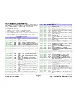
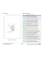
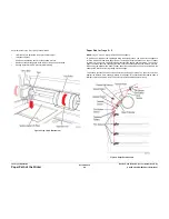
Paper Size Sensor
Figure 14 Paper Size Sensor P/J Location
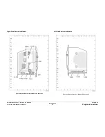
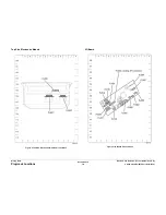
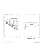
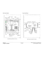
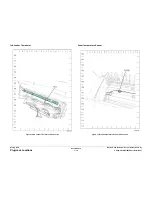
Wire Routing Diagrams
Table 1 Wire Routing Location
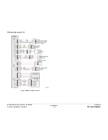
P/J
Map
Remarks
P/J101
Figure 1
Connects the I/O Board to the Outer Duplex Guide.
P/J101
Figure 5
Connects the Outer Duplex Guide to the I/O Board.
P/J102
Figure 1
Connects the I/O Board to the Waste Tray Detect Sensor.
P/J103
Figure 2
Connects the Purge Pump to the Power Control Board (Electronics Mod-
ule).
P/J105
Figure 2
Connects the Electronics Module Fan to the Left Side Harness.
P/J106
Figure 2
Connects the Media Path Motor to the Left Side Harness.
P/J107
Figure 2
Connects the Head Tilt Solenoid to the Left Side Harness.
P/J108
Figure 2
Connects the Tray 2 Lift Motor to the Left Side Harness.
P/J109
Figure 2
Connects the Tray 2 Pick Clutch to the Left Side Harness.
P/J110
Figure 2
Connects the Tray 1 Pick Solenoid to the Left Side Harness.
P/J110
Figure 6
Test points - No connection.
P/J111
Figure 2
Connects the Deskew Clutch to the Left Side Harness.
P/J112
Figure 2
Connects the Preheater Lift Solenoid to the Left Side Harness.
P/J113
Figure 2
Connects the Optional Feed Tray to the Left Side Harness.
P/J114
Figure 1
Connects the Drum Heater to the Front Side Harness.
P/J115
Figure 3
Connects the Paper Preheater to the Front Side Harness.
P/J115
Figure 3
P/J116
Figure 5
Connects the Exit Door Sense Switch to the Top Front Harness.
P/J117
Figure 1
Connects the Front Door Sensor to the Top Front Harness.
P/J117
Figure 5
P/J118
Figure 3
Connects the Process Motor/ Encoder to the Right Side Harness.
P/J119
Figure 1
Connects the Head Maintenance Clutch to the Right Side Harness.
P/J120
Figure 1
Connects the Drum Heater Dump Load to the Right Side Harness.
P/J121
Figure 1
Connects the Strip Solenoid to the Right Side Harness.
P/J122
Figure 1
Connects the Drum Encoder to the Right Side Harness.
P/J123
Figure 1
Connects the X-Axis Motor to the Right Side Harness.
P/J125
Figure 3
Connects the Preheater Temperature Thermistor, Preheat Sensor, and
Deskew Entry Sensor to the I/O Board.
P/J125
Figure 4
P/J126
Figure 3
Connects the Tray 2 Paper Height Sensor to the Right Side Harness.
P/J127
Figure 3
Connects the No Paper Sensor to the Right Side Harness.
P/J128
Figure 3
Connects the Preheat Deskew Sensor to the Right Side Harness.
P/J130
Figure 6
Connects the Ink Level Sense probes to the Printhead
P/J132
Figure 6
Connects the Printhead and Electronics Module to the Jetstack Fuse.
P/J180
Figure 6
Connects the Printhead to the Main Controller Board (Electronics Mod-
ule).
P/J190
Figure 6
Connects the Printhead Thermistor to the Printhead.
P/J201
Figure 6
Connects the Power Supply (Electronics Module) to the Printhead.
P/J240
Figure 6
Connects the Printhead Heater to the Wave Amplifier.
Содержание COLORQUBE 8570
Страница 1: ...ColorQube 8570 8870 Printer ColorQube 8570 8870 Service Manual Xerox Internal Use Only...
Страница 2: ......
Страница 152: ...October 2012 3 2 ColorQube 8570 8870 Service Manual Revised 3rd Revision Xerox Internal Use Only Image Quality...
Страница 196: ...October 2012 4 2 ColorQube 8570 8870 Service Manual Revised 3rd Revision Xerox Internal Use Only Repairs and Adjustments...
Страница 304: ...October 2012 5 2 ColorQube 8570 8870 Service Manual Revised 3rd Revision Xerox Internal Use Only Parts List...
Страница 316: ...October 2012 6 2 ColorQube 8570 8870 Service Manual Revised 3rd Revision Xerox Internal Use Only General Troubleshooting...
Страница 372: ...October 2012 7 2 ColorQube 8570 8870 Service Manual Revised 3rd Revision Xerox Internal Use Only Wiring Data...
Страница 392: ...October 2012 8 2 ColorQube 8570 8870 Service Manual Revised 3rd Revision Xerox Internal Use Only Theory of Operation...
Страница 423: ......